4. Before starting ...
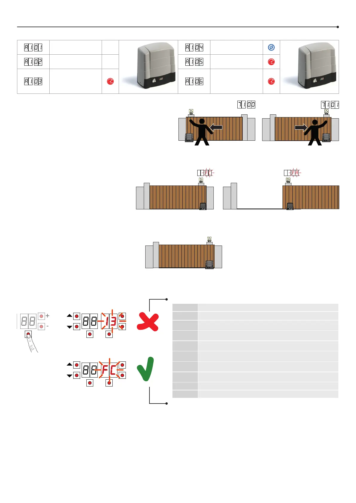
a) Select the automation system model installed with the parameter .
PROG TEST
+
-
TEST
+
-
GATE OPENS TO LEFT
GATE OPENS TO RIGHT
BG30/1600 BG30/1400/R
BG30/2200 BG30/1800/HS
BG30/1000/HS BG30/1500/HS
d) Move the gate into the completely CLOSE position.
Check that, by pressing the TEST button, the display
always shows FC.
e) Press the TEST button.
Possible alarms and safety device messages:
SEE ACQUISITION PROCEDURE
b) Select the position of the motor relative to the gate with the parameter
. The default setting for this parameter is with the motor installed on
the right hand side of the gate (seen from interior side).
c) Adjust the (mechanical or magnetic) limitswitches
so that, once triggered, the gate stops slightly
before it reaches the mechanical stop.
CLOSING LIMIT SWITCH
OPENING LIMIT SWITCH
00
No safety device in alarm state and no limit switch activated.
Sb (Sb)
Release handle or lock open.
STOP contact (N.C.) open.
Jumper the STOP contact.
5
Sensing edge contact COS1 (N.C.) is open. Check connection. If sensing
edge is not installed, disable with 3 00.
4
Sensing edge contact COS2 (N.C.) is open. Check connection. If sensing
edge is not installed, disable with 4 00.
3
Photocell contact FT1 (N.C.) is open. Check connection. If photocell is not
installed, disable with 50 00.
2
Photocell contact FT2 (N.C.) is open. Check connection. If photocell is not
installed, disable with 53 00.
fe
Both limit switches in error state. Check connections and settings of limit
switches.
fa
If gate is open, gate open limit switch is detected.
fC
If gate is closed, gate closed limit switch is detected.