3.3 Power supply
Controllers require 12VDC nominal power supply. The power should be connected to the +12V line
and -12V line. Additionally, the -12V line can be used as reference potential for the RS485 bus, IN1-
IN3 input lines and RACS LCK/DTA bus.
The power supply can be provided by means of power supply unit (e.g. PS-15DR, PS20) which can
be equipped with backup battery in order to ensure operation of access control in case of power
failure.
Note: All devices connected to RS485 bus (including controllers) should have the same supply
minus (GND). In order to ensure this, all the GND terminals from various power supply units within
the system should be connected with each other using separate wire. Alternatively, the common
supply minus of the entire system can be earthed however only in one point.
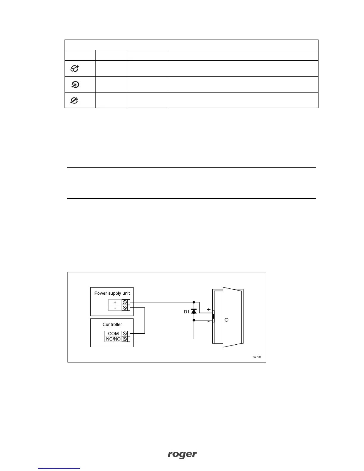
3.4 Connection of door lock
In majority of cases, door locking devices are inductive type. It means that overvoltage (voltage
surge) can occur when current flow is interrupted and it can interfere with the controller electronic
components. In extreme cases it may result in improper operation of the controller or even freeze.
Moreover, overvoltage condition causes quicker wear of relay contacts. In order to limit this
adverse effect, it is necessary to use a general type semiconductor diode e.g. 1N4007 (one piece of
such diode is included with the controller). The diode should be connected as close as possible to
the inductive element (electric strike or magnetic lock).
Fig. 2 Connection of door lock
3.5 Communication with controller
RS485 bus and UT communication interface (e.g. UT-2USB) are used for communication with
controller. Single RS485 bus creates network (subsystem) and up to 32 controllers with unique
addresses in range of 00.99 can be connected to the bus. For the communication with distant
subsystems it is required to use UT-4DR or UT-4 v2.0 communication interface or CPR32-NET
network controller as all of them enable communication through computer network (LAN or WAN).