Operating Concepts
R&S
®
NRP Series
40Getting Started 1419.0170.02 ─ 12
If you want to use an android device like a tablet or a smartphone, use the
R&S Power Viewer Mobile. For details, see Chapter 6.6, "R&S Power
Viewer Mobile", on page 42.
Setup
Figure 6-3: Setup with the R&S Power Viewer
1 = Signal source
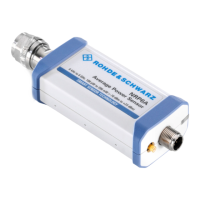
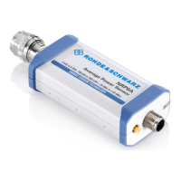
2 = R&S NRP power sensor
3 = Host interface connector
4 = R&S NRP‑ZKU cable
5 = USB connector
6 = Computer with installed R&S Power Viewer
Incorrectly connecting/disconnecting the R&S NRP power sensors can
damage the power sensors or lead to erroneous results.
Ensure that you connect/disconnect your power sensor as described in
Chapter 4, "Preparing for Use", on page 10.
Starting a measurement
1. Connect the cables as shown in Figure 6-3.
For a detailed description, refer to Chapter 4.6.1.1, "Simple USB Connection",
on page 14.
2. Start the R&S Power Viewer.
3. Execute zeroing:
Note: Turn off all measurement power signals before zeroing. An active mea-
surement signal during zeroing causes an error.
a) Switch off the measurement signal.
R&S Power Viewer

 Loading...


