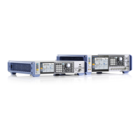
Instrument tour
R&S
®
SMA100B
40Getting Started 1419.8620.02 ─ 10
Use this interface to connect a computer for remote control of the R&S SMA100B.
To set up the connection, use high-quality shielded cables. See "Cable selection
and electromagnetic interference (EMI)" on page 21.
See also "Annex: Hardware interfaces" and chapter "Network and remote control"
in the user manual.
USB/USB In
●
Female USB (universal serial bus) 2.0 connector of type A (host USB), to con-
nect devices like a keyboard, a mouse, a memory stick, or the R&S NRP-
Z3/Z4 cable for the R&S NRP power sensors
●
Option: R&S SMAB-B86
Female USB 3.0 connector of type Micro-B (USB In), for example, for remote
control.
How to: Chapter 4.8, "Connecting USB devices", on page 23
LAN
RJ-45 connector to connect the R&S SMA100B to a LAN for remote control,
remote operation, and data transfer.
How to: Chapter 4.7, "Connecting to LAN", on page 22
Ref In/Ref Out
Input/output for external reference signal.
BNC connectors for reference signals from 1 MHz to 100 MHz.
SMA connectors for 1 GHz reference signals.
How to: Chapter 4.11, "Connecting to Ref In/Ref Out", on page 26
V/GHz X-Axis
BNC connectors for output of a voltage ramp signal:
●
"V / GHz": the voltage is proportional to the frequency.
●
"X-Axis": output of a voltage ramp for the X deflection of an oscilloscope or an
XY recorder.
Z-Axis
BNC connector for output of a voltage pulse signal, e.g. for the combined blank-
ing and marker generation of network analyzers.
Stop
BNC connector for input and output signals to stop a sweep in all modes.
Rear panel tour

 Loading...