EasyManuals Logo

Roland GX-24 Manual

Roland GX-24
20 pages
To Previous Page IconTo Previous Page
Page #20 background imageLoading...
Page #20 background image
3-5
3-2 MAIN BOARD_REPLACEMENT
3
4
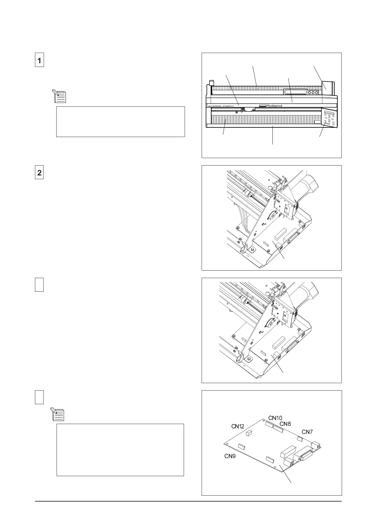
Connect the CABLEs to the MAIN BOARD.
Disconnect the CABLEs from the MAIN BOARD.
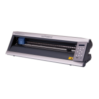
Remove the RIGHT SIDE COVER, PANEL, TOP
COVER, TOP PANEL, UNDER PANEL, FRONT
APRON and REAR APRON.
Replace the MAIN BOARD to the new one.
MAIN BOARD
TOP PANEL
TOP COVER
FRONT APRON
REAR APRON
UNDER PANEL
PANEL
RIGHT SIDE COVER
MAIN BOARD
Make sure to disconnect the Cables
connected to the PANEL from the MAIN
BOARD.
MAIN BOARD
CARRIAGE CABLE : CN7
CARRIAGE MOTOR CABLE : CN8
PAPER SENSOR CABLE : CN9
FEED MOTOR CABLE : CN10
FAN CABLE : CN12

Other manuals for Roland GX-24

Questions and Answers:

Question and Answer IconNeed help?

Do you have a question about the Roland GX-24 and is the answer not in the manual?

Roland GX-24 Specifications

General IconGeneral
Cutting SpeedUp to 20 inches/sec (500 mm/sec)
Distance Accuracy±0.004 inches (±0.1 mm) or less
Repeatability±0.1 mm (0.0004 in.) or less
InterfaceUSB
Power SupplyAC 100-240V, 50/60Hz
Operating Temperature5 to 40°C (41 to 104°F)
Operating Humidity35 to 80% RH (non-condensing)
Software Resolution0.025 mm/step (0.001 in./step)