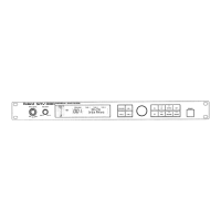
8
May,1999SRV-3030/3030D
SYSTEM SOFTWARE UPDATE USING THE SMF /
//
/
SMF によるシステムソフトウェアのアップデートについて
によるシステムソフトウェアのアップデートについてによるシステムソフトウェアのアップデートについて
によるシステムソフトウェアのアップデートについて
TEST MODE /テストモード
/テストモード/テストモード
/テストモード
♦
Updating the system software using SMF
The system software of SRV-3030/3030D can be updated
by using the latest version of standard MIDI file.
The update disc (P/No.17048598) contains the following
SMF data:
SRV030-1.MID
SRV030-2.MID
SRV030-3.MID
SRV030-4.MID
Updating procedure
♦
Through MIDI
1. Connect MIDI IN of SRV-3030/3030D to MIDI OUT of the
sequencer through the MIDI cable.
2. While holding down CATEGORY, UNIT A/B and
SYSTEM buttons, turn on POWER switch.
3. Turn NUMBER/ knob to display "UPDATE from MIDI" on
the screen.
4. Press NUMBER/ knob to start loading.
5. Play the sequencer.
6. Upon completion of play, set the sequencer to stop
mode.
♦
Updating by using the upgrading memory card
(P/No.17048599)
1. Insert an upgrading memory card (smart media) into
MEMORY CARD slot.
2. While holding down CATEGORY, UNIT A/B and
SYSTEM buttons, turn on POWER switch.
3. The LCD will display "UPDATE from CARD". Press
NUMBER/ knob to start updating.
◆
◆◆
◆
SMF
によるシステムソフトウェアのアップデート
によるシステムソフトウェアのアップデートによるシステムソフトウェアのアップデート
によるシステムソフトウェアのアップデート
SRV-3030/3030D
は、スタンダード
MIDI
ファイルで供給
される最新のシステムを使ってシステムソフトウェアの
アップデートが可能です。
アップデートディスク(
P/No.17048598
)には、次のよう
な
SMF
データが保存されています。
SRV030-1.MID
SRV030-2.MID
SRV030-3.MID
SRV030-4.MID
次の手順でシステムソフトウェアのアップデートを行って
ください。
◆
◆◆
◆
MIDI
による方法
による方法による方法
による方法
1.シーケンサの
MIDI OUT
と
SRV-3030/3030D
の
MIDI
IN
を接続します。
2.
[CATEGORY]+[UNIT A/B]+[SYSTEM]
ボタンを押しなが
ら、電源を入れます。
3.
[NUMBER ([PAGE])]
ツマミを回して、
LCD
画面表示を
"UPDATE from MIDI"
にします。
4.
[ENTER (PUSH)]
ボタンを押して、
"LOAD"
状態にしま
す。
5.シーケンサを
"PLAY"
状態にします。
6.データ再生が終了しましたら、シーケンサを
"STOP"
状
態にします。
◆メモリーカード
◆メモリーカード◆メモリーカード
◆メモリーカード
(P/No.17048599)
による方法
による方法による方法
による方法
1.バージョンアップ用のメモリーカード(スマートメディ
ア)を差し込みます。
2.
[CATEGORY]+[UNIT A/B]+[SYSTEM]
ボタンを押しなが
ら、電源を入れます。
3.
LCD
画面表示が
"UPDARE from CARD"
になりますの
で、
[ENTER (PUSH)]
ボタン
を
押すとバージョンアップ
が実行されます。
♦
Before entering test mode
•
Tools required
Oscilloscope, noise meter, distortion meter, amps,
speakers, smart media (S2M-5, S4M-5), stereo connection
cables, mono connection cables, MIDI-capable equipment,
MIDI cable, expression pedal (EV-5 or equivalent), foot
switch (DP-2, FS-5U, etc.)
EV-5: set MIN knob to "0".
FS-5U: set the polarity switch to the position close to the
jack.
Using connection cables with standard plug, connect INPUT
A to OUTPUT A and INPUT B to OUTPUT B.
Using connection cables with MIDI CONNECTOR, connect
MIDI IN to MIDI OUT.
♦
ENTERING TEST MODE (B) (B: USER TEST MODE)
While holding CUSTOM, MEMORY and BYPASS buttons,
turn on POWER switch.
Select the test option by turning NUMBER/ knob. Follow the
instruction given in the selected page.
If the unit fails a test, turn off the unit, take corrective action
and then restart the test.
Pages
1: Sequential test - factory test
2: LCD test
3: Switch test
4: DRAM test (self-test)
5: Flash test (self-test)
6: MIDI test (self-test)
7: Card test (self-test) - factory test
8: DSP test (self-test)
9: GA test (self-test)
10: I/O test (self-test)
◆テストモードに入る前の準備
◆テストモードに入る前の準備◆テストモードに入る前の準備
◆テストモードに入る前の準備
・使用機材
・使用機材・使用機材
・使用機材
オシロスコープ、ノイズメーター、歪率計、アンプ、ス
ピーカー、
EXP PEDAL
、
FOOT SWITCH
、
MIDI CABLE
•
To start test sequence
Press NUMBER/ knob.
1: Sequential test - factory test (skip this option)
2: LCD test
All dots increase and then decrease contrast twice.
Visually check for contrast and missing dots.
3: Switch test
Operate the following controls and check the results
indicated on the LCD. The next test can be started when
the current control passes the test.
PARAM 1: Check to see that the reading changes for
0 to 100 to 0.
PARAM 2: Check to see that the reading changes for
0 to 100 to 0.
PARAM 3: Check to see that the reading changes for
0 to 100 to 0.
NUMBER/: Gradually turn the knob clockwise until three clicks
are felt and then counterclockwise for three clicks.
Verify the resulting changes.
While observing the LCD screen, turn on and off the
following switches one by one in the order given.
[ENTER]
→
[BANK]
→
[CATEGORY]
→
[MEMORY]
→
[SYSTEM]
→
[PREVIEW]
→
[BYPASS]
→
[UNIT A/B]
→
[CUSTOM]
→
[EZ EDIT]
Depress and release the foot switch.
When all switches have passed the test, the test 4 will
automatically start. As the name implies, a self-test
requires only selecting and starting signal from NUMBER/
knob (simply press the knob).
4: DRAM test (self-test)
5: Flash test (self-test)
6: MIDI test (self-test)
7: Card test (self-test) - factory test (skip this option)
8: DSP test (self-test)
9: GA test (self-test)
10: I/O test (self-test)
11: Analog characteristics test
•
Residual noise
With the unit in THRU mode.
Using the noise meter, measure the noise level at
balanced OUTPUT A (connect across HOT and GND, and
COLD and GND). The readings must be -80 dBm or
below. Repeat the measurement for balanced OUTPUT B.
The difference between OUTPUT A and B in readings
must be 2 dBm or below.
•
Total distortion factor (distortion factor)
With the unit in THRU mode.
Connect a 600( shunt resistor to balanced INPUT A.
Set the distortion meter: output = sine wave, 1 kHz, +4
dBm, HPF = 400 Hz, LPF = 30 kHz.
Measure distortion through balanced INPUT A to
OUTPUT A (HOT and GND and COLD and GND). Verify
0.02% or less distortion factor.
Repeat measurements for INPUT B to OUTPUT B.
・各テスト項目選択方法
・各テスト項目選択方法・各テスト項目選択方法
・各テスト項目選択方法
[ENTER (PUSH)]
ボタンでスタートします。
1:シーケンシャル・テスト(工場でのみ行います。)
2:
LCD
テスト
全ドットが段々に明暗(2回)します。
コントラスト、ドットの欠けを目視で確認します。
3:
SW
テスト
以下の操作を順次行います。
それぞれ
"OK"
であれば順次テストが進みます。
PARAM 1
:
0
→
100
→
0
まで、変化することを確認し
ます。
PARAM 2
:同上
PARAM 3
:同上
EXP.PEDAL
:同上
NUMBER (PAGE)
:右にゆっくり3クリック以上、左に
ゆっくり3クリック以上、変化を確認
します。
下記順に各
SW
を押して離します。
各項目に対応した内容が、
LCD
画面に表示されます。)
[ENTER]
→
[BANK]
→
[CATEGORY]
→
[MEMORY]
→
[SYSTEM]
→
[PREVIEW]
→
[BYPASS]
→
[UNIT A/
B]
→
[CUSTOM]
→
[EZ EDIT]
FOOT SWITCH
踏んで離します。
以下の(セルフテスト)は、項目ごとに自動的にテスト
されます。
別の項目に進む場合は、
[ENTER (PUSH)]
ボタンを押しま
す。
4:
DRAM
テスト(セルフテスト)
5:
FLASH
テスト(セルフテスト)
6:
MIDI
テスト(セルフテスト)
7:
CARD
テスト(工場でのみ行います。)
8:
DSP
テスト(セルフテスト)
9:
GA
テスト(セルフテスト)
10:
I/O
テスト(セルフテスト)
11:アナログ特性テスト
・残留ノイズの測定
スルー状態にて、
OUTPUT A , B (
バランス接続
)
の残
留ノイズをノイズメーターで測定し、
"-80dBm"
以下で
あることを確認して下さい。
また
A , B
の値の差を
"2dBm"
以内とします。
HOT-GND , COLD-GND
間の値を個々に測定。)
・歪率(全歪率)の測定
スルー状態にて、
INPUT A - OUTPUT A
(バランス接
続)
, INPUT B-OUTPUT B
(バランス接続)間の歪率
を歪率計にて測定し、
"0.02%"
以下であることを確認
して下さい。
(
HOT - GND , COLD - GND
間の値を個々に測定し、
入力側は
"600
Ω
"
でシャント状態にて測定します。)
*歪率計のセッティング:出力信号
正弦波
1kHz
+4dBm , HPF 400Hz LPF 30kHz ON
 Loading...