7
RS-232 Command Reference
Using the RS-232 connector, you can operate the V-1SDI remotely from an external device.
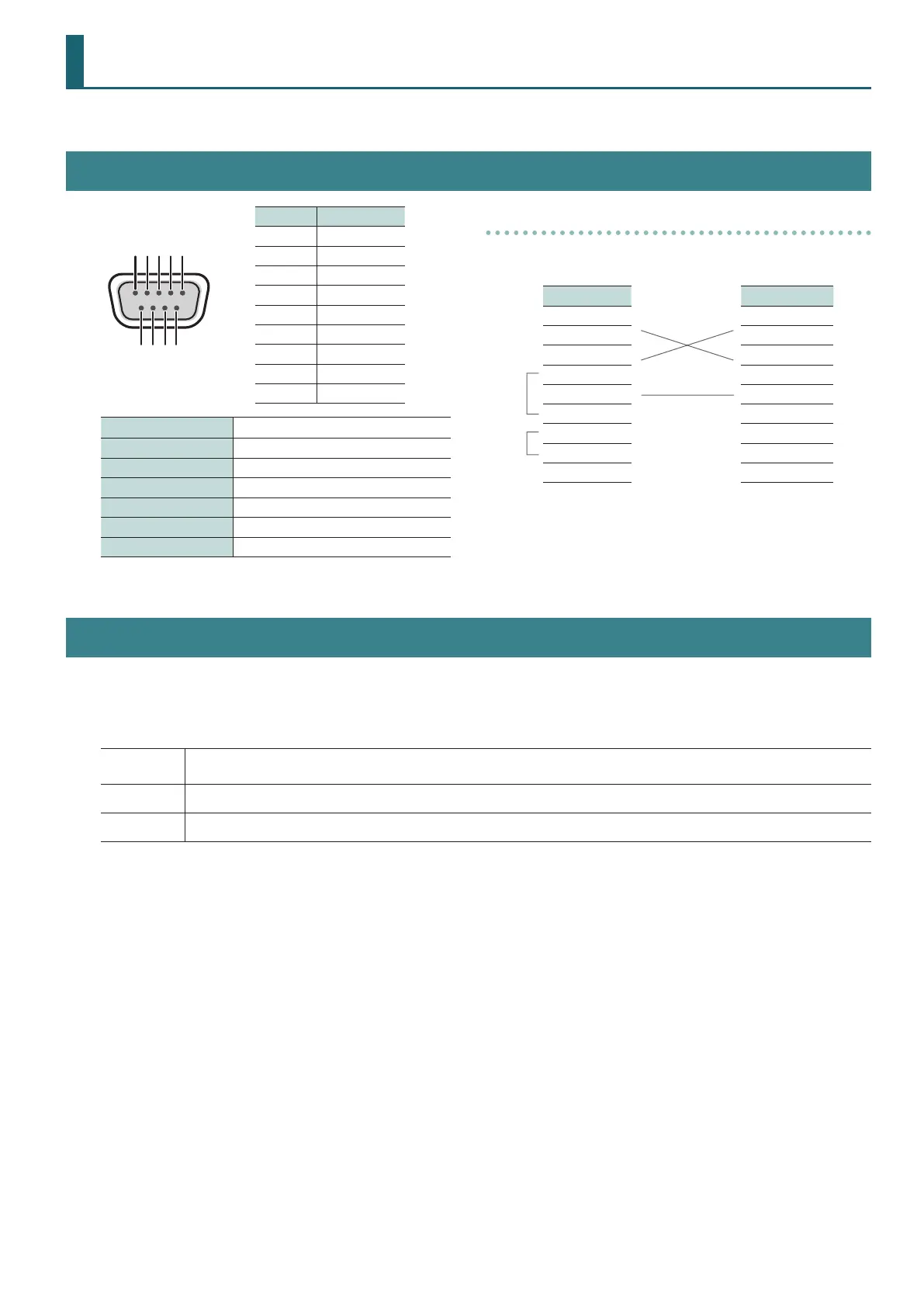
Specification of the RS-232 Connector
D-sub 9-pin (male)
Pin No. Signal
1 N.C.
2 RXD
3 TXD
4 DTR
5 GND
6 DSR
7 RTS
8 CTS
9 N.C.
Communication method Synchronous (asynchronous), full-duplex
Communication speed 9600 bps
Parity none
Data length 8 bit
Stop bit 1 bit
Code set ASCII
Flow control XON/XOFF
Cable Wiring Diagram
Wire the three lines of RXD, TXD, and GND as shown in the gure
below.
V-1SDI Controller
N.C.: 1 1:
RXD: 2 2: RXD
TXD: 3 3: TXD
DTR: 4 4:
GND: 5
5: GND
DSR: 6 6:
RTS: 7 7:
CTS: 8 8:
N.C.: 9 9:
* The connections between 4 and 6 and between 7 and 8 are
inside the V-1SDI.
* When connecting to a controlling device (such as an RS-232
compatible computer), use a crossover cable.
Overview of Commands
Commands are each formatted as an ASCII code string composed of “stx” plus “three alphabetic letters (capitals)” plus “;” (semicolon).
The three letters of the alphabet indicate the type of command.
If the command has an argument, a colon (“:”) is inserted between the command letters and the argument. When multiple arguments occur, they are
separated by commas (“,”).
stx
An ASCII-code signal name (code number: 02H), this is a control code indicating the start of a command. “H” indicates that it is a
hexadecimal value.
:
This is the code that the V-1SDI recognizes as a separator between a command and its argument.
;
This is the code that the V-1SDI recognizes as the end of a command.
* The codes of stx (02H), ACK (06H), and Xon (11H)/ Xo (13H) are the control codes.
* When successively sending commands to the V-1SDI from an external device, after each command, be sure that “ACK” is returned before sending the
next command.
 Loading...