21
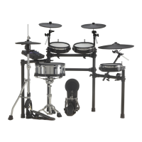
TD-20
6. SW/LED Test [TEST - 6 SW&LED]
1. Press each panel switch one at a time; confirm that the switch name and
position appears in the display, and the corresponding sound plays.
Also confirm that the corresponding light goes off.
Example of the [EXIT] button being pressed
fig.test-11
LEDs with no corresponding switches are turned off with the following
switches.
TRIGGER METER LEDs: Turned off one by one from the top by pressing
the [F1] button
Left column of seven-segment LED: The dots are turned off one by one
by pressing the [F2] button
Center column of seven-segment LED: All of the dots go off
simultaneously by pressing the [F3] button
Right column of seven-segment LED: All dots go off simultaneously by
pressing the [F4] button
GROUP FADERS Upper LEDs: Turned off by the [+] button
GROUP FADERS Lower LEDs: Turned off by the [-] button
CompactFlash LED: Turned off by the [PREVIEW] button
2. The velocity check is simultaneously performed with the [PREVIEW]
button.
Tap the [PREVIEW] button strongly; confirm that “127” appears in the
lower right of LCD display.
fig.test-12
3. If all tests result in “OK,” the procedure automatically advances to the
next test category.
If two or more switches are pressed simultaneously, the test is cancelled.
7. FOOT SW Test [TEST - 7 FOOT SW]
1. Connect two FS-5Us to the PCS-31, one to the white and on to the red
plugs, and connect the black plug to the FOOTSW INPUT.
2. Press each FS-5U, one at a time; the corresponding location in the LCD
display should show “ON/OFF.”
If both foot switches are on simultaneously, “SHORT!” appears in the display;
“OK” is not displayed.
When both foot switches show “OK,” the following appears in the LCD
display.
fig.test-13
3. When the cable is disconnected from the INPUT the procedure
automatically advances to the next test.
8. LCD/ENCODER Test [TEST - 8 LCD&ENCDR]
1. Slowly rotate the [VALUE] dial to the right.
2. Confirm that the arrow in the middle of the LCD display moves slowly to
the right, while the screen contrast darkens.
3. When the meter is rotated fully to the right, “RIGHT!” appears in the
display, and then changes to “OK!”
4. Next, slowly rotate the [VALUE] dial to the left.
5. Confirm that the arrow in the middle of the LCD display moves slowly to
the left, while the screen contrast lightens.
6. When the meter is rotated fully to the left, “LEFT!” appears in the display,
and then changes to “OK!”
fig.test-14
7. Next, press the [F1(DARK)] button.
Confirm all dots in the LCD are lit.
8. Next, press the [F1(BRIGHT)] button.
Confirm all dots in the LCD go off.
9. Press the [F5(OK)] button to advance to the next test.
9. SLIDER Test [TEST - 9 SLIDER]
1. Move each GROUP FADER up and down one at a time.
2. Confirm that when the FADER is all the way up, the corresponding value
in the LCD is “127,” and when the FADER is all the way down, the
corresponding value in the LCD is “0.
Also confirm that this is accompanied by the corresponding pitch
changes.
fig.test-15
3. When all FADER changes are detected, the procedure automatically
advances to the next test.
10. HH CTRL Test [TEST - 10 HH CTRL]
1. Connect a FD-7 to the HH CTRL INPUT with a monaural cable.
2. Gradually press the FD-7 down and confirm that the meter in the LCD
gradually decreases, with the meter at “0” when the pedal is fully pressed
down.
Here, the following appears in the LCD display.
 Loading...