16 • Physical Installation NK-VRC User Guide (v05)
1. The Heartbeat
The NK-VRC indicates its status using a pulsating front panel LED called the Heartbeat. This is a white LED
that softly pulsates to show that the device is operational. It will quickly flicker to show the following events:
• NK switch or status response
• Configuration command addressed to this device
• Third party crosspoint switch command received
2. Reset Button
The reset button will force a hard reset of the device. It is slightly recessed to prevent accidental operation.
3. Communication Activity LEDs
The Communication (Comms) activity LEDs light to report communication activity:
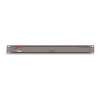
Rear Panel Overview
The NK-VRC rear panel provides two T-BUS ports and a PSU port.
Figure 3.5 NK-VRC — Rear Panel
1. Power Connector
The supplied power connects here.
2. T-Bus Ports
These are RJ-45 sockets for connecting to the T-Bus. T-Bus is a multi-drop RJ-45 control system supporting
collision detection and half-duplex communication. The T-Bus Control System minimizes cable connections
between devices, acting as both a reliable means to provide phantom power to devices and as the
communications line.
Installing the NK-VRC into a Routing Switcher System
The NK-VRC may be installed anywhere within the routing switcher system using its T-Bus connectors on the rear
panel.
To connect the NK-VRC into a routing switcher system
1. Install the NK-VRC into the rack frame.
2. Fix the NK-VRC in place with appropriate fasteners.
3. Connect a straight CAT5 Ethernet cable between a T-Bus connector on the rear panel of the NK-VRC and a
T-Bus connector on the rear panel of another NK Series device.
Table 3.1 Comms Activity LEDs
LED Monitors Details
A Third-Party Rx Serial data is being received from third-party device.
B Third-Party Tx Serial data is being transmitted to third-party device.
C NK Rx Serial data is being received from NK Control System.
D NK Tx Serial data is being transmitted to NK Control System.
POWER
T-BUS
 Loading...