Controller Operation
AYC-Ex5/T65 Series Installation and Programming Manual 43
4.9.9 Defining the Auxiliary Input and Output
The default auxiliary setting is 2004.
To define the auxiliary input and output:
1. Enter Programming mode.
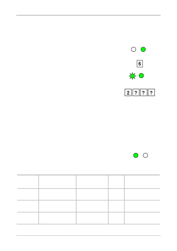
2. Press 6 to enter Menu 6.
The left LED flashes green.
3. Construct a code using the following
instructions:
Second digit (Auxiliary Mode)
In addition to the Lock Strike Relay and Lock Strike REX, the
unit features an Auxiliary Input. The Auxiliary mode defines
the function of the Auxiliary Input.
Third and fourth digits (Auxiliary Setting)
Each of the Auxiliary modes has a 2-digit setting that
affects how the Auxiliary mode functions (Table 5).
You hear three beeps.
The system returns to Normal mode.
Table 5: Quick Reference Guide for Auxiliary Mode Setting
Aux.
Mode
Aux. Input
Function
Aux. Output
Activated by
Aux.
Relay
Aux. Settings
(in seconds)
0 AUX REX Valid code or
N.O. 01 to 99 Aux.
1 Normal/Secure
switch
Valid code N.O. 01 to 99 Aux.
relay release time
2 Normal/Secure
switch
Star button (*) N.O. 01 to 99 Aux.
relay release time
 Loading...