EasyManua.ls Logo

Rosslare AYC-F64 User Manual

Rosslare AYC-F64
60 pages
To Next Page IconTo Next Page
To Previous Page IconTo Previous Page
Page #39 background imageLoading...
Page #39 background image
Controller Functionality
AYC-Fx4 and AYC-Gx4 family manual Page 38
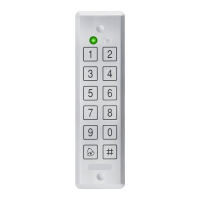
3) Construct a code using instructions hereafter.
First Digit
For fail secure operation, the first digit is set to 0.
For failsafe operation, the first digit is set to 1.
Second Digit
Siren Time in minutes (1-9, 0-disabled)
Third and Fourth Digits
Enter the number of seconds (from 1 to 99) that
you want the Lock Strike to be released.
For example, 0312 means Fail Secure Operation, a 3-minute Siren,
and a 12-second Lock Strike release time.
4) System returns to its normal mode.
You will hear three beeps.
The Door LED will turn off.
The Mode LED will turn green.
Note:
Default value is 0004 which corresponds to Fail Secure
operation, no siren, and 4-seconds Lock Strike release time.
6.9.10. Defining the Auxiliary Input and Output
The default auxiliary setting is 2004.
1) Enter the Programming
Mode.
2) Press 6 to enter Menu 6.
The Mode LED will flash
green
?
?
?
?
6
Mode/Transmit
Door/Program
Green
Mode/Transmit
Door/Program
Green
Mode/Transmit
Door/Program
Green
Green

Table of Contents

Other manuals for Rosslare AYC-F64

Question and Answer IconNeed help?

Do you have a question about the Rosslare AYC-F64 and is the answer not in the manual?

Rosslare AYC-F64 Specifications

General IconGeneral
ModelAYC-F64
Number of Doors Supported1
Operating Humidity0 to 95% (non-condensing)
KeypadYes
Protection ClassIP65
Operating Voltage12V DC
Input Voltage12 to 24 VDC
Operating Temperature-31°C to 63°C (-25°F to 145°F)
TamperOptical Back Tamper Detection
Dimensions120mm x 76mm x 21mm (4.72" x 2.99" x 0.83")
Operating Current65mA
Communication InterfaceWiegand 26-Bit

Summary

General Information

1.1 Introduction

Overview of the AYC-Fx4/AYC-Gx4 series as waterproof, convertible reader/controllers.

1.2 Reader/Controller Types

Details the different models and their capabilities, like PIN only or Proximity card support.

1.3 Box Content

Lists the items included in the product package for verification.

1.4 Ancillary Equipment

Specifies required external equipment for installation and operation.

Technical Specifications

2.1 Key Features

Highlights primary features like built-in reader, backlit keypad, tamper sensor, and lockout capability.

Electrical Characteristics

Provides specifications for power supply, voltage range, and current draw.

Environmental Characteristics

Details operating temperature, humidity, and outdoor suitability (IP-65).

Mechanical Specifications

Lists physical dimensions and weight for different models.

Installation

3.1 Mounting the AYC-Fx4 and AYC-Gx4

Instructions and guidance on selecting a location and drilling mounting holes for the devices.

Wiring Instructions

Wiring Guide and Diagrams

Explains cable preparation, splicing, and provides visual diagrams for controller and reader applications.

Reader Functionality

5.1 Transmit Mode

Describes the reader's state for receiving data from cards or PIN entries.

5.2 Programming the AYC-Fx4/AYC-Gx4 Series

Outlines the keypad-driven menu system for configuring reader settings and formats.

Selecting Keypad Transmission Format

Details the process for choosing one of eight keypad data transmission formats.

Selecting Proximity Card Transmission Format

Explains how to select between 26-Bit Wiegand, Clock & Data, or Wiegand Card + PIN formats.

Changing Codes and Settings

Covers modifying programming codes, facility codes, and returning to factory defaults.

Lost Code Recovery

Provides procedures for recovering lost programming or normal/secure codes.

Controller Functionality

6.1 User Levels and Modes

Explains user types (Normal, Secure, Master) and operational modes (Normal, Bypass, Secure).

6.3 Auxiliary Input & Output

Describes how auxiliary inputs/outputs can be configured for various functions.

6.4 Door Alarms

Details the generation of door alarms based on door position switches and delay timers.

6.5 Internal Tamper Detection

Covers tamper events triggered by unauthorized opening or removal of the unit.

6.6 Lockout Feature

Explains how the system enters lockout mode after multiple incorrect code entries.

6.7 Request to Exit (REX) Function

Details the operation of the REX button for door unlocking based on fail-safe/secure settings.

6.8 Secure Application Appurtenances

Explains the role of companion devices for secure access control and communication.

6.9 Programming the AYC-Fx4/AYC-Gx4

Introduces the keypad-driven programming menu system for advanced controller configurations.

Programming Menu Overview

Lists all available programming menus and their default factory settings.

Mode Entry and Exit Procedures

Steps for entering and exiting the controller's programming mode.

Code Management

Procedures for changing Lock Strike, Auxiliary, Programming, Normal/Secure, and Normal/Bypass codes.

Operation Settings

Configuration for Fail Safe/Secure, Tamper Siren, and Auxiliary Input/Output settings.

User Management

Instructions for enrolling and deleting primary and secondary user codes.

Relay Assignments

Methods for assigning relay activation codes for Lock Strike and Auxiliary relays.

PIN Code and Defaults

Covers setting PIN code length and returning to factory default settings.

Lost Code Recovery

Procedures for replacing lost programming or normal/secure codes.

Limited Warranty

Appendix A. Limited Warranty

Details the terms and conditions of the five-year limited warranty for the product.

Exclusions and Limitations

Lists specific conditions and situations not covered by the product warranty.

Limited Warranty Terms

Outlines the scope, disclaimers, and legal terms of the limited warranty.

Technical Support

Appendix B. Technical Support

Provides contact information and locations for obtaining technical assistance.

Related product manuals