Installation
14 AYC-Qx4 Family Installation and Programming Manual
8. Carefully re-attach the front cover of the unit.
9. Secure the front cover by using the supplied security Torx screw.
A Torx security screw tool is provided to tighten the security Torx
screw.
3.2 Wiring Instructions
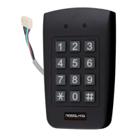
The unit is supplied with a 6-conductor 56-cm (22-in.) pigtail with
exposed wires coated with solder.
3.2.1 Wiring the Unit as a Reader
If you connect the unit to a standard access control unit, it
automatically functions as a reader.
To connect the unit as a reader (to a controller):
1. Select the appropriate connections according to Table 1.
Table 1: Wiring the Reader to the Controller
Wire Color Function
Black/Shield Ground (-)
Red Vin (+)
Green Data 0/Data (D0)
White Data 1/Clock (D1)
Brown LED control
Purple Tamper
2. Prepare the controller cable by cutting the cable jacket back 3.2
cm (1¼”) and strip the wire 1.3 cm (½”).
3. Splice the reader’s pigtail wires to the corresponding controller
wires and cover each joint with insulating tape.
4. If the tamper output is being utilized, connect the purple wire to
the correct input on the controller.
5. Trim and cover all conductors that are not used.

 Loading...
