3
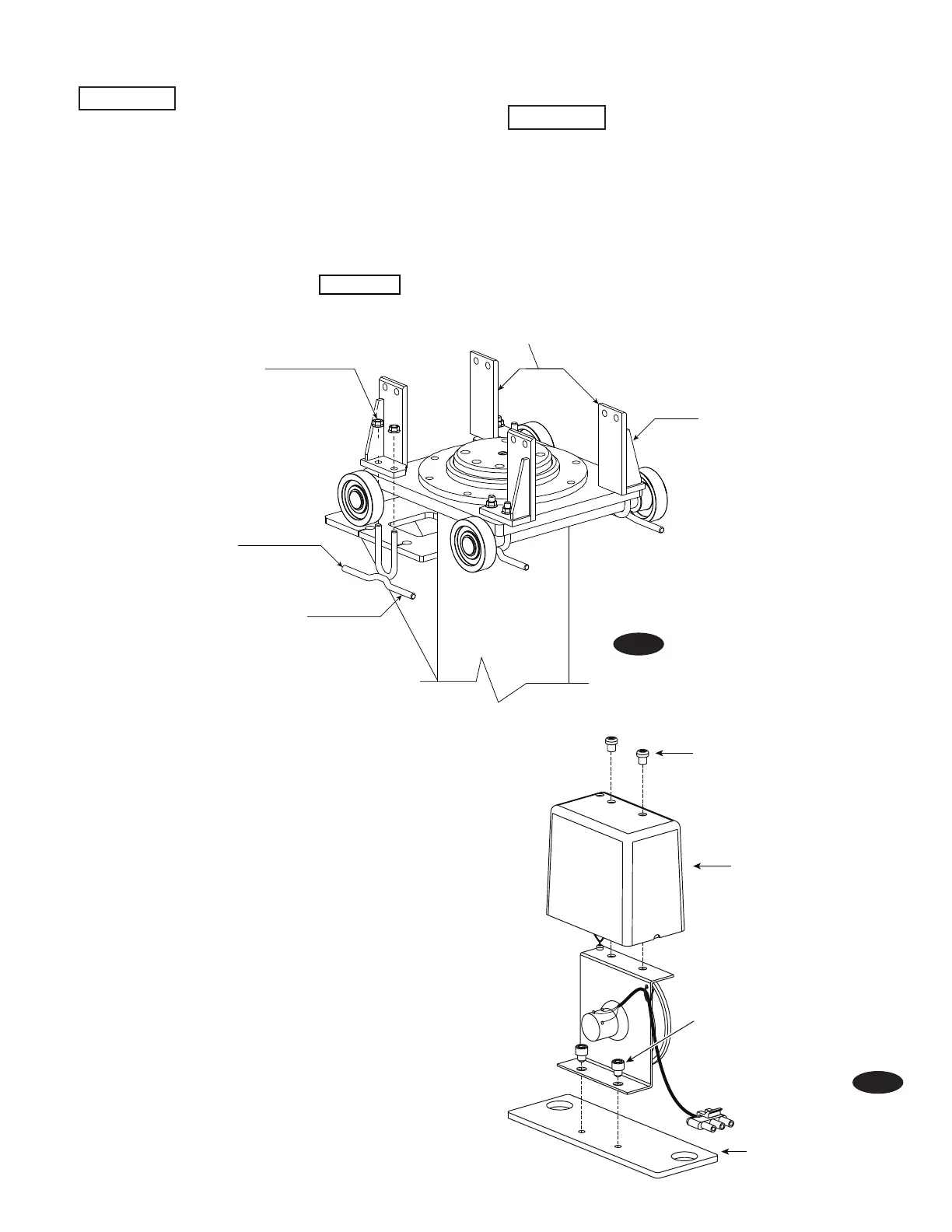
Remove Screws
From Top of
Post Position Sensor
Remove Cover
Insert (2)1/4"-20NC x 1/4" Lg.
HEX SHCS Through
Position Sensor
And Attach To Post
Position Sensor Adapter
Post Position Sensor
Adapter
1/2"-13NC Whizlock
Hex Nut
Torque to 35 ft. lbs.
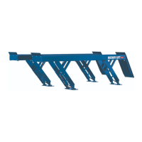
Welded On Brackets
Faces Outward
Shutter Plate Brackets
(2) Each Side
Bracket Supports
Face Outward
Axle/Chain Adjustment
Bracket
Do Not Tighten Fasteners Completely.
Adjustments Will Be Made After Shutter Plate Installation.
IMPORTANT
Fig. 2
Fig. 3
Step 2: Installing Bracket Supports And Axle/Chain Adjustment
Brackets
IMPORTANT
All components should be installed with posts
laying down. This prevents the piston in the post from pushing
out too much hydraulic fluid while installing the male adapter and
hydraulic hose. This is important to the bleeding procedure done
later in the installation. It also helps prevent damage to the air
line elbow attached to the bottom of the lock assembly.
Note: Posts are the same for all housings. Determine which
post you are going to install in the moveable housings and install
bracket supports and axle/chain adjustment brackets.
Check for damage of coating on posts. Contact
Rotary Lift if you have any concerns.
A.) Install bracket supports and axle/chain adjustment brackets
with (8) 1/2" whizlock hex nuts torque to 35 ft-lbs., Fig. 2 .
Step 3: Installing Post Position Sensors Onto Post Position
Sensor Adapters:
A.) Remove covers from post position sensors, Fig. 3.
B.) Attach post position sensors onto post position sensor
adapters with 1/4"-20NC x 1/4" Lg. Hex SCHS, Fig. 3.

 Loading...