13
L1
PE
L2
L3
1
3
5
2
4
6
MOTOR
1
3
5
2
4
6
OVERHEAD SWITCH
(WHERE APPLICABLE)
DRUM
SWITCH
3 Phase
Supply
L1
PE
L2
L3
1
3
5
2
4
6
MOTOR
1
5
7
2
6
8
OVERHEAD SWITCH
(WHERE APPLICABLE)
DRUM
SWITCH
3 Phase
Supply
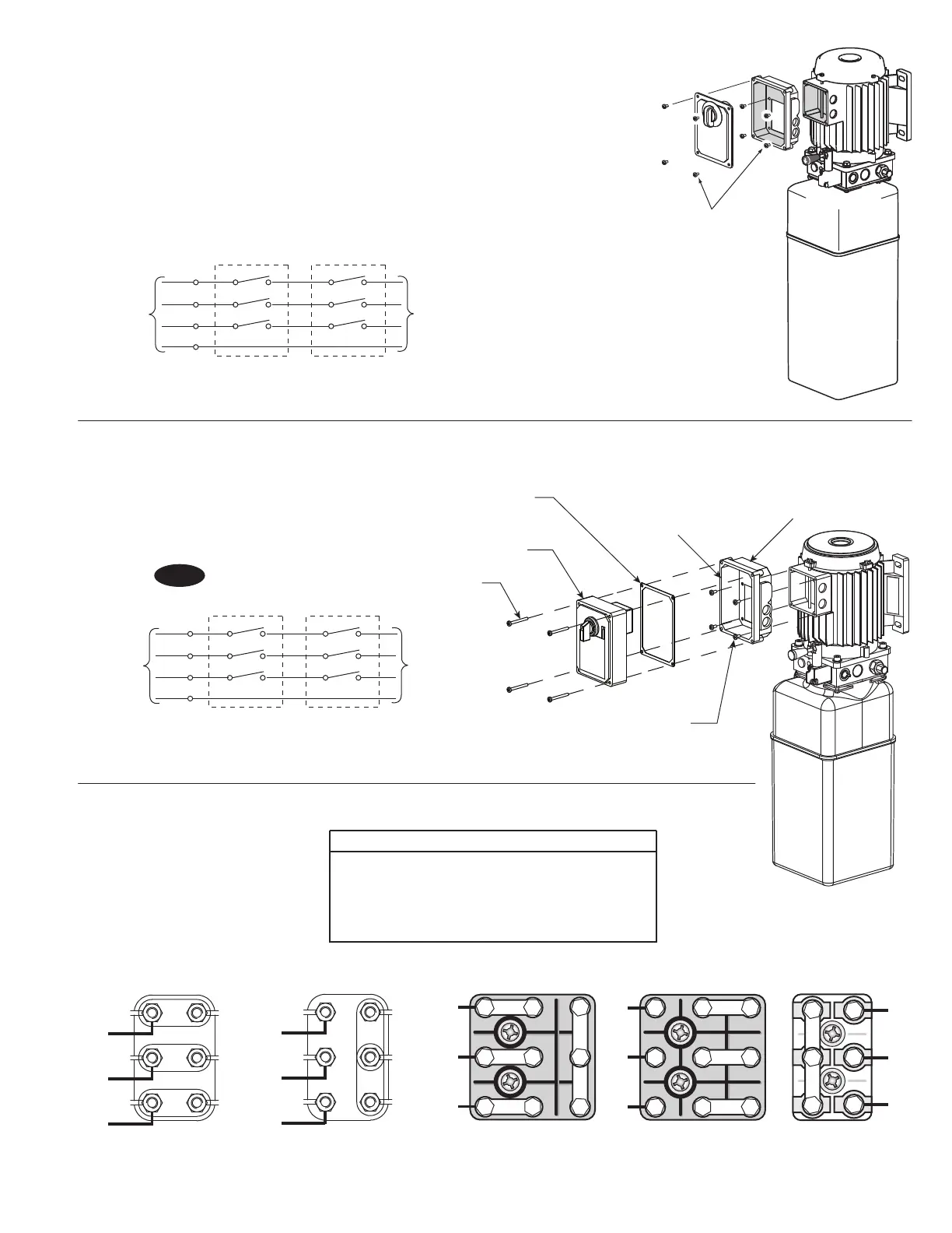
Capacitor Box Attachment
Option One
FOR 3 Ø POWER
UNITS: Attach Box using
M5 x 10 PHMS, Plated
NOTES:
1. Unit not suitable for use in unusual conditions. Contact
Rotary for moisture and dust environment duty unit.
2. Control Box must be field mounted to power unit.
3. Motor rotation is counter clockwise from top of motor.
NOTE: Two Different Drum Switches were used
please select one of the two options below.
Newer model three phase lifts use the push button
control box with contactor. Its instructions follow
the Drum Switch instructions.
(4) M5 x 45 PHMS, Plated
(4) M5 x 10 PHMS, Plated
Capacitor Box To Power Unit
Drum Switch
And Cover
Re-seal Between
Box And Spacer
With Silicone
Sealer
Capacitor
Box
Gasket
T1
T2
T3
U2
V2
W2
W1
V1
U1
575V 60 Hz. 3Ø
Three Phase Power Unit
MOTOR OPERATING DATA TABLE - THREE PHASE
LINE VOLTAGE RUNNING MOTOR VOLTAGE RANGE
208-240V 50/60Hz. 197-253V
400V 50Hz. 360-440V
440-480V 50/60Hz. 396V-528V
575V 60Hz. 518V-632V
L1
L2
L3
L1
L2
L3
208-240V
50/60Hz. 3Ø
440-480V 50/60 Hz. 3Ø
380-400V 50 Hz. 3Ø
Current Pin Layouts Older Pin Layouts
W2
U2
V2
W2
U2
V2
U1
V1
W1
U1
V1
W1
T7
T1
T8
T2
T9
T3
T4
T5
T6
L1
L2
L3
T7
T4
T1
L1
T8
T5
T2
L2
T9
T6
T3
L3
208-240V
50/60Hz. 3Ø
440-480V 50/60 Hz. 3Ø
380-400V 50 Hz. 3Ø
Fig. 22

 Loading...


