12
15. Wheel Spotting Dish: Position wheel spotting dish
as illustrated in Fig. 1a or 1b. Drill (2) 3/8" holes 2-1/2"
deep in concrete floor using holes in wheel spotting dish
as guide. Drive both anchors, provided, into concrete to
secure dish.
16. Arm Restraints & Superstructure: Before
installing arms, install arm Restraint Gears as follows:
Install Restraint Gear into arm clevis, as shown in Fig. 17,
so that the rounded edge (top side) of the gear teeth is
facing upward. Then, install the (2) 3/8"-16NC x 1-1/2"
HHCS (8 total for all 4 arms) and 3/8" Spring
Lockwashers into the gear and arm as illustrated Fig. 17,
but do not tighten.
After installing Restraint Gears, raise carriages to a
convenient height. Grease swivel arm pins and holes with
Lithium grease. Raise Gear Block by pulling upward on
pin-ring to allow enough clearance for the Restraint Gear
and arm to slide into the yoke clevis and under the teeth
of the Gear Block, Fig. 18. Install 1-1/2" diameter arm
pin(s) and 3/16" x 2" cotter pin(s), Fig. 19. After
installing arm pin, torque the two Restraint Gear bolts to
30-34 ft.-lbs. Let the Gear Block down allowing the teeth
of the Restraint Gear and Gear Block to mesh together,
Fig. 18.
17. Oil Filling & Bleeding: Use Dexron III ATF, or
Hydraulic Fluid that meets ISO 32 specifications.
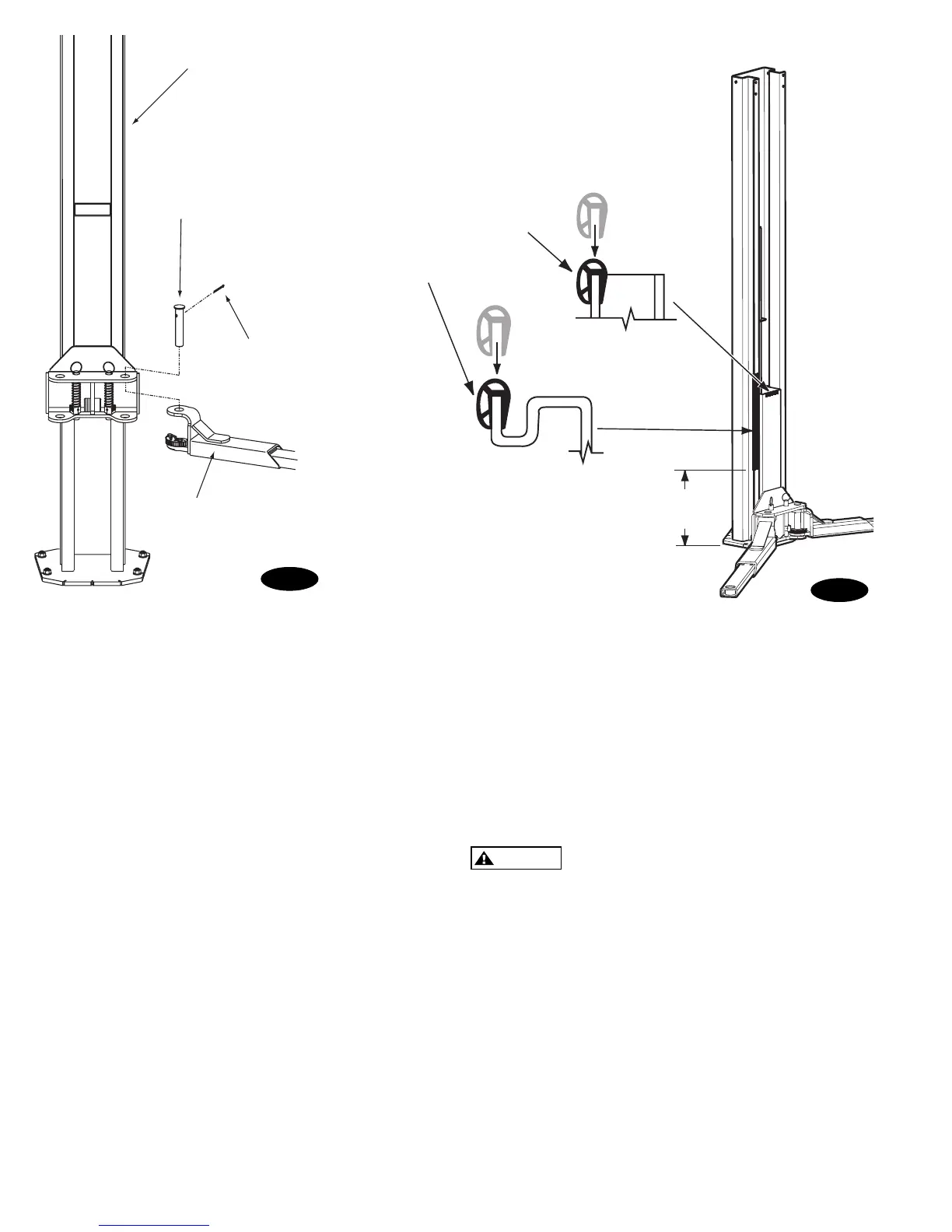
Column
Arm Pin
Cotter Pin
Arm
Long Bumper
Short
Bumper
Padded section
of door bumper
faces out.
21"
(533mm)
Fig. 19
Fig. 20
Remove fill-breather cap (and fill vent screw for Fenner
Power Unit), Fig. 7a or Fig. 8a. Pour in (8) quarts of
fluid. Start unit, raise lift about 2 ft. Open cylinder
bleeders approx. 2 turns, Fig. 9b.
Close bleeders when fluid streams. Fully lower lift. For
Fenner Power unit, add more fluid until it comes out fill
vent hole. All others fill until it reaches the MIN______
mark on the tank. System capacity is (13) quarts. Replace
fill-breather (and fill vent screw for Fenner Power Unit).
CAUTION
If fill-breather cap is lost or broken, order
replacement. Reservoir must be vented.
18. Door Bumper Installation:
A) Press long bumper on column edge, Fig. 20.
B) Press short bumper on top edge of carriage tube, Fig.
20.
19. Latch Cable Adjustment:
A) Check to make sure the latch will properly engage
and disengage. Slowly release the latch handle. A 1/8
gap between the top of the latch dog and the column
is allowable.
B) When raising, listen to latches to be sure that both
latch dogs fall into latch slots. If they do not, loosen
clamp and adjust tension as necessary.
C) Install left latch cover using 5/16-18NC x 3/8 lg
PHMS.
 Loading...


