13
PUSH TO
RELEASE
LATCHES
RAISE LIFT
OFF LATCHES
NP266
P
U
S
H
T
O
R
E
L
E
A
S
E
L
A
T
C
H
E
S
RAISE LIFT
OFF LA
TCHES
N
P
2
66
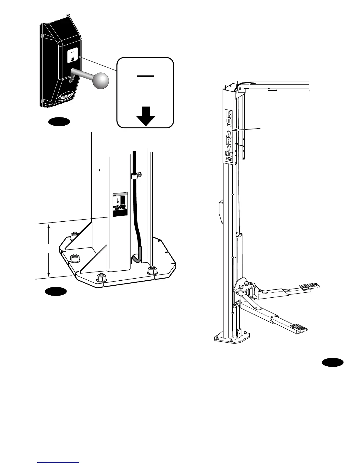
Fig. 21
ROTARY IDENTIFICATION
At Completion of Installation,
Place ROTARY Decal on
Lift as Shown Below
Fig. 23
Rotary Decal
Fig. 22
W
A
R
N
IN
G
Keep feet
clear of lift
while lowering
8"
20. Pressure Test: Run lift to full rise and keep motor
running for 5 seconds. Stop and check all hose
connections. Tighten or reseal if required. Repeat air
bleeding of cylinders.
21. Equalizer Cable Adjustment: Raise lift to check
equalizer cable tension. Below carriage, grasp adjacent
cables between thumb and forefinger, with about 15 lbs.
effort you should just pull the cables together. Adjust at
upper tie-offs Fig. 10a.
22. Latch Release Decal: If latch release decal is not
already installed, then install on cover above latch release
handle, Fig. 21.
23. Pinch Point Decal Location: Install enclosed pinch
point decals. Place (1) decal on each column, Fig. 22.
Decals should be a minimum of 8 from the bottom of
decal to the ground.
24. Rotary Decal Location: Clean area where decals are
to be placed. Remove backing from decals. Position and
apply on approach sides of each column extension as
indicated, Fig. 23, and press flat.
 Loading...


