8
12. Electrical: Have a certified electrician run
appropriate power supply to motor, Fig. 21 & 22. Size
wire for 20 amp circuit. See Motor Operating Data Table.
Never operate the motor on line voltage less
than 208V. Motor damage may occur.
IMPORTANT: Use separate circuit for each power unit.
Protect each circuit with time delay fuse or circuit breaker.
For single phase 208-230V, use 20 amp fuse. Three phase
208-240V, use 20 amp fuse. For three phase 400V and
above, use 10 amp fuse. For wiring see Fig. 21 & Fig. 22.
All wiring must comply with NEC and all local electrical
codes.
Note: 60Hz. single phase motor CAN NOT be run on
50Hz. line without a physical change in the motor.
13. Overhead switch: Check overhead switch assembly
to assure that switch bar is depressing switch plunger
sufficiently to actuate the switch. The overhead switch
is wired normally open, see Fig. 15a, Fig. 16a, and Fig.
16b. Lift will not operate until weight of switch bar is
depressing switch plunger. Verify that Power Unit stops
working when switch bar is raised, and re-starts when the
bar is released.
When bleeding, hold a shop cloth over
bleeder screw to buffer the air and fluid while bleeder
valve is open.
14. Oil Filling & Bleeding: Use Dexron III ATF, or
Hydraulic Fluid that meets ISO 32 specifications. Remove
fill-breather cap, Fig. 15b. Pour in (8) quarts of fluid.
Start unit, raise lift about 2 ft. Open cylinder bleeders
approx. 2 turns, Fig. 9.
Close bleeders when fluid streams. Fully lower lift. Add
more fluid until it reaches fill line on the tank. System
capacity is (14) quarts. Replace fill-breather cap.
If fill-breather cap is lost or broken, order
replacement. Reservoir must be vented.
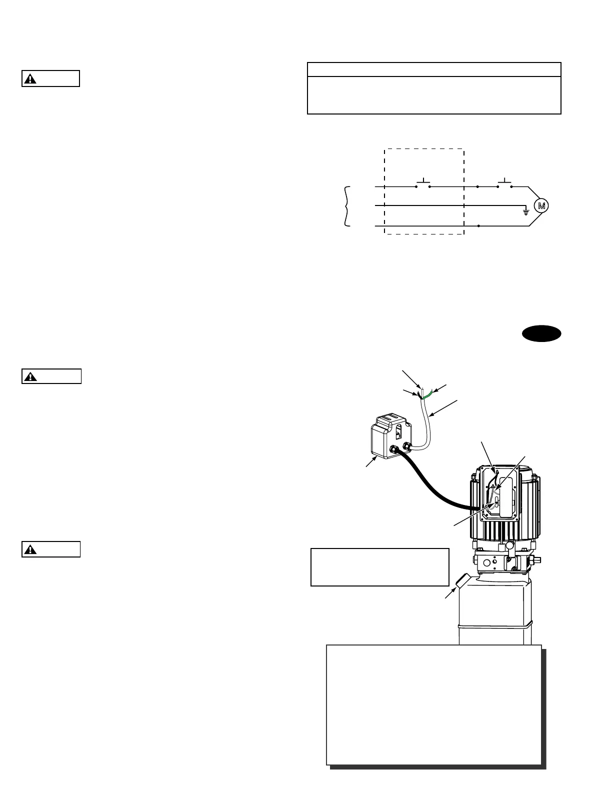
Single Phase Power Unit
MOTOR OPERATING DATA TABLE - SINGLE PHASE
LINE VOLTAGE RUNNING MOTOR VOLTAGE RANGE
208-230V 50Hz. 197-253V
208-230V 60Hz. 197-253V
Note: 60Hz. Single phase motor CAN NOT be run on
50Hz. line without a physical change in the motor.
Overhead Switch
Max. Voltage: 277V
Max. Current: 25A
Connect supply to wires in box as
per Fig. 22. Attach ground wire to
screws provided.
Fill Breather Cap
Attach ground wire here.
208-230V 60Hz
Single Phase
Attach black wire
to black wire.
Attach white
wire to red wire
.
Black
Green
White
M
230V
60Hz
1 Ø
Black
Green
White
Overhead
Limit Switch
Up
Switch
White
Black
Black
NOTE: Assure cord used for connection
between the overhead switch and powe
r
unit is of the type specified in:
UL201, Sections 10.1.1.3 & 10.1.1.4
(Example: SO, G, STO) Size
for 25 amp
circuit. See UL 201, Section 15 for proper
wiring requirements for this connection.
Fig. 15b

 Loading...


