7
Fig. 6
600-6350 Series lifts 4-Post lifts “without lift
table” nr. 1 spacer
A
1
600-6350 Series lifts 4-Post lifts “without
lift table” nr. 2 screws (Length = 16mm /
0.63”)
B
0.06”
WHEEL-FREE JACK IN “WORKING POSITION”
0.63”
1
Fig. 7
WHEEL-FREE JACK IN “CHECK POSITION”
2
600 Series lifts
(with platform edge
H=70 mm-2.75”)
600 Series lifts
6350 Series lifts
(with platform edge
H=38 mm-1.5”)
4-Post lifts
(without lift table)
2
2
0.47”
1
1
0.75”
2
4-Post lifts (with lift
table)
0.39”
1
1 1
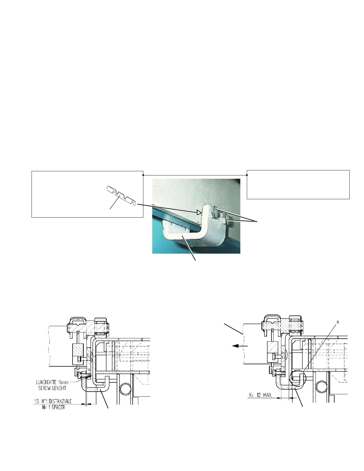
Fig. 8
Holder brackets adjustment
a) Complete holder brackets 1 Fig. 6 assembly inserting
shims.
A. Tighten screws B.
(Refer to Fig. 6 and 7) Interpose n°1 shims A, with the
screws B of suitable length (16mm-0.63”). Screws
shall not protrude out wheel-free jack bracket, so as
not to damage platforms side surface.
b) Repeat the procedure also on the opposite side.
c) Ref. Fig. 7. Slide wheel-free jack along the whole
platform, making sure it moves properly. Holder
bracket 1 does not have to interfere with platform
edge.
Ref. Fig. 8. While wheel-free jack is sliding onto plat-
form, check X value in different positions.
To carry out this check, move both wheel-free jacks
sliding members 2 away from platforms, with holder
brackets 1 resting onto platforms inner edges (see
area A).
If value X is higher than the specified one, move slid-
ing members in working position, and add one more
spacer. Then, re-check X value.
 Loading...