4 x Operation
23
BA ROTEX GSU - 09/2007
• Determine the hydraulic resistance in the heating network.
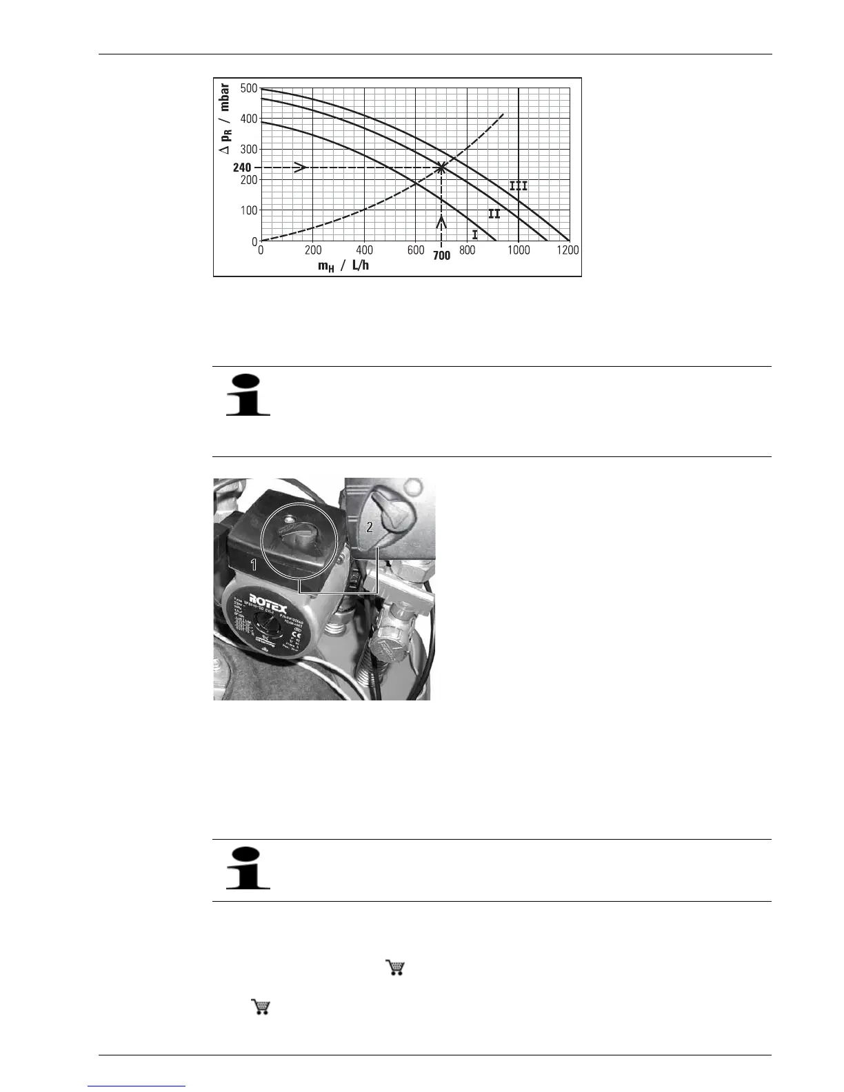
• Determine the needed output stage of your heating pump by using Fig 4-6.
• Set the pump to the required output stage (Fig 4-7).
Example for the determination of the pump output stage
– Heat requirement: 13 kW, design temperatures: 75/60 °C, Scatter: 15 K, required throughput quantity : 700l/h, hydraulic
resistance in the heating network: 240 mbar.
Î As designed, pump stage 2 is sufficient. Even pump stage 1 can suffice during the transition period.
4.2.3 Information on operating noises
In some cases, resonance in the flue gas system can amplify the noise at the mouth of the flue gas duct. The noise level can be
effectively reduced by using a silencer ( 15 45 78).
Air suction noises are generated in ambient air-dependent operations. The noise level can be effectively reduced by using a
silencer ( 15 45 77).
Δp
R
Residual discharge head m
H
Flow rate
Figure 4-6 Residual discharge head of ROTEX GSU heating pump
In practice, the hydraulic resistance in the heating network is often not known. By observing the flow and return
temperature at the heat generator, you can define whether the pump can still provide sufficient output at a lower
speed stage.
The difference between the flow and return temperatures must not be greater than the design scatter, and each
room must still be adequately heated.
1 Heating pump
2 Setting lever for pump output stage
Figure 4-7 Setting the pump output stage
The 35 kW versions have a controlled heating pump for which the heating engineer makes the optimum setting
at the time of commissioning. It is also possible to set the pump output stage manually, but it is not necessary.