7 x Technical Data
43
BA ROTEX GSU - 09/2007
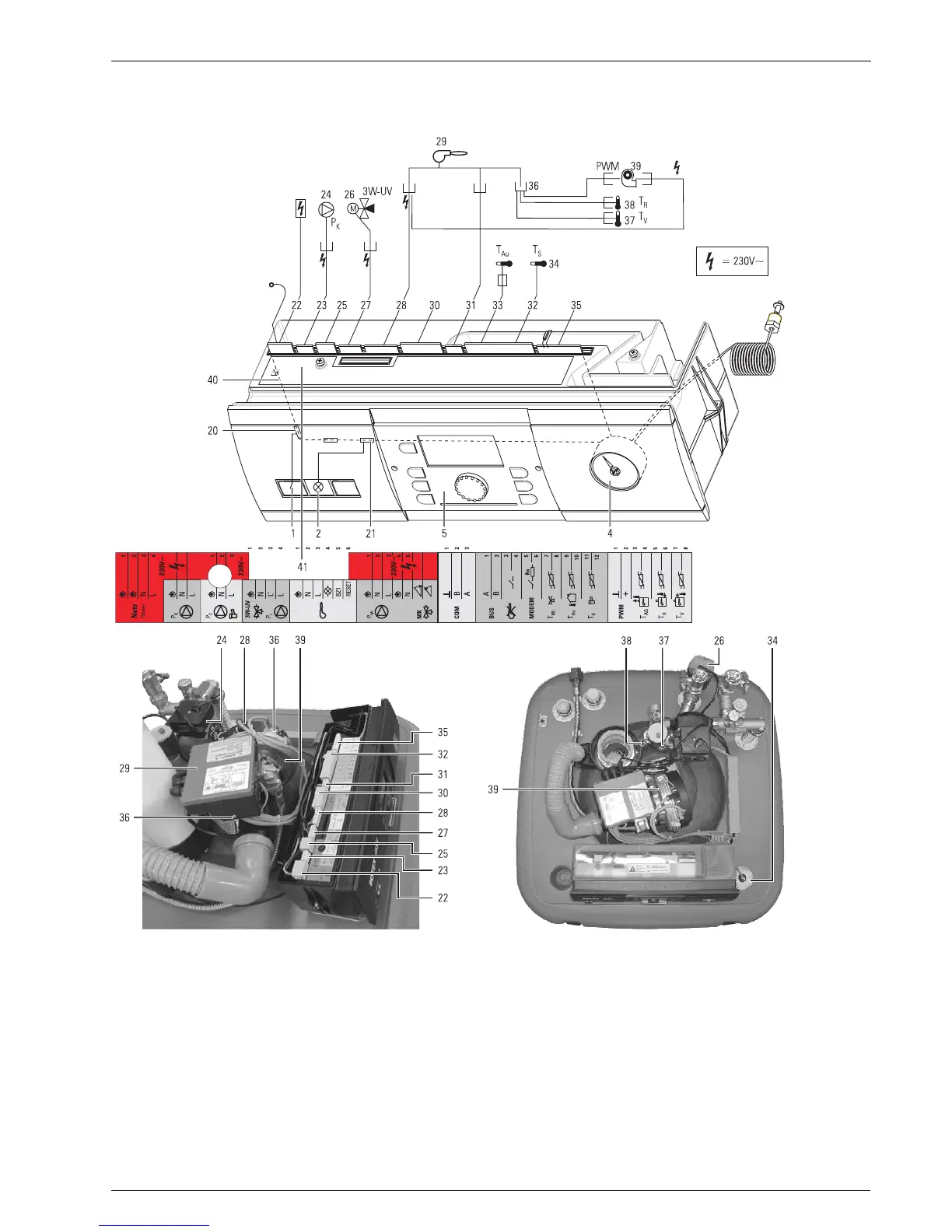
7.2 Wiring diagram
1 Mains power switch
2 Common fault indicator
4 Capillary tube pressure gauge
5 Control: Central unit THETA 23R
20 4-pin circuit board connector with switch cable
21 4-pin circuit board connector with fault indicator
cable
22 4-pin mains circuit board connector with clamped
mains cable and earthing connection
23 3-pin circuit board connector with pump cable
24 Heating circulation pump
25 3-pin circuit board connector for connecting a
circulation pump
26 3-way diverting valve
27 4-pin circuit board connector with valve cable
28 6-Pin circuit board connector with connected
burner cable (voltage supply for automatic firing
unit and burner fan)
29 Modulating gas burner automatic firing unit
30 7-pin circuit board connector for connecting a
mixer motor and mixer circulation pump
31 3-pin circuit board connector with communication
cable
32 12-pin circuit board connector for clamping
sensors, BUS and control lines
33 External temperature sensor
34 Storage tank temperature sensor
35 8-pin circuit board connector with terminating
resistor or flue gas temperature sensor (optional)
36 16-pin MOLEX plug with cable for flow and return
flow temperature sensor as well as fan control
37 Flow temperature sensor
38 Return flow temperature sensor
39 Burner fan
40 Control panel circuit board
41 Stickers for terminal assignment
Figure 7-13 Wiring diagram (showing the control THETA 23R)