38
FA ROTEX GW - 09/2012
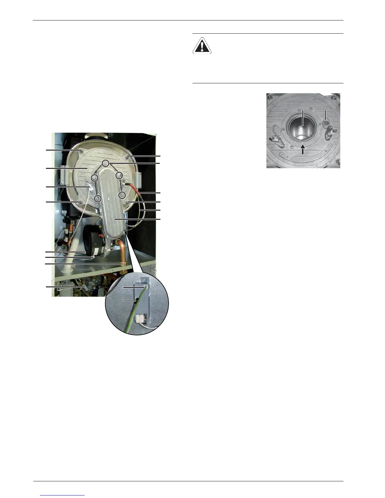
7 x Gas burner
Burner dismantling
Ɣ Close the gas isolator valve.
Ɣ Switch off the ROTEX GW and secure against restart.
Ɣ Create access to the unit internals (see chapter 4.9.3).
Ɣ Disconnect the ionisation electrode (fig. 7-6, item 14) at the
plug (fig. 7-6, item 14/1) and pull into the top boiler chamber.
Ɣ Disconnect the ignition line (fig. 7-6, item 1) at the ignition
transformer.
Ɣ Disconnect the earth wire (fig. 7-6, item 2) at the ignition
transformer.
Ɣ Disconnect the plug for blower control (fig. 7-6, item 3) and
the mains plug for the blower (fig. 7-6, item 4).
Ɣ Unscrew the top burner gas supply line (fig. 7-6, item 5).
Ɣ Release the 4 nuts (fig. 7-6, item 7).
Ɣ Lift the burner flange (fig. 7-6, item 6) with burner from the
burner chamber.
If you detect damage to the flame tube insert (fig. 7-7, item 1) it
must be replaced. To do this, you must remove the burner flange
channel (fig. 7-6, item 8) (5 screws, fig. 7-6, item 9).
Burner installation
Ɣ Check the gas line for leakage.
Ɣ Start the burner. Check for function, leakage at the burner
flange and the settings (see chapter 7.3.2).
Fig. 7-6 Dismantling the burner
WARNING!
An incorrect burner removal and installation can lead
to gas leakages.
Ɣ All metric screwed connections must be secured
when installing against coming loose using screw
locking lacquer.
Ɣ Carry out burner fitting in
reverse order to the
removal of the burner.
– Take account of the
mounting position
(item 2) of the flame
tube.
– The sight glass
(item 3) over the igni-
tion electrodes must
be clean and be in
perfect condition.
Fig. 7-7 Sight glass + mounting
position of the flame tube
1