37
FA ROTEX GW - 09/2012
7 x Gas burner
7.3.6 Setting the gas pressure controller
The gas valves are factory-set. As a rule, no changes should be
made to the gas pressure controller. The adjusting screw
(fig. 7-1, item 12) is hidden under a cover.
If the set value for basic load deviates to much from the target
value or if the burner tends to whistle:
Ɣ Adjust the adjusting screw for the gas pressure controller
(fig. 7-1, item 12) in small steps (maximum half a turn per
adjustment step).
Ɣ After each adjusting step, wait at least 2 minutes.
Ɣ Check the changes in the combustion quality with a flue gas
analyser.
7.3.7 Setting ignition and Ionisation electrodes
The electrodes are factory-set.
For adjusting:
Ɣ Remove the burner (see chapter 7.4)
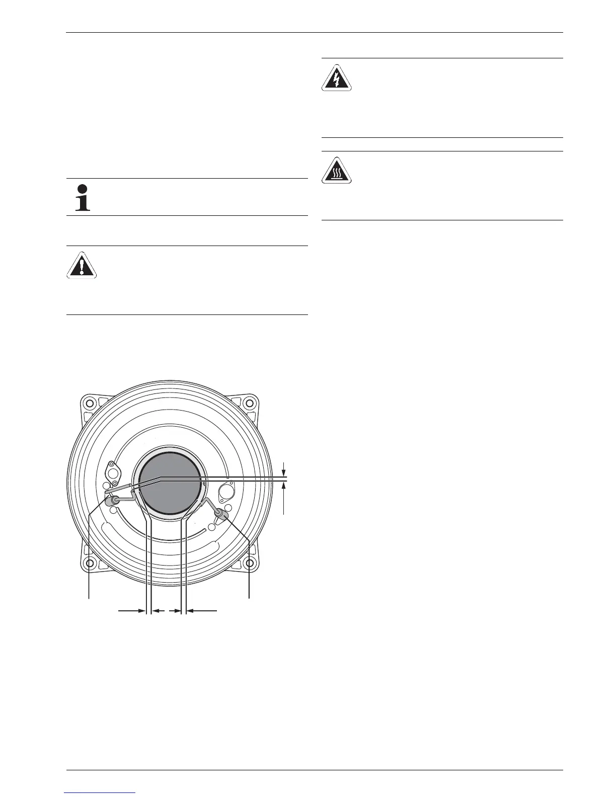
Ɣ Check and adjust the electrodes (see fig. 7-5).
7.4 Dismantling the burner
The burner works, as a rule, almost without any wear and
residue. It may be necessary to dismantle the burner for some
cleaning and servicing jobs or if there is damage in the
combustion chamber area.
If the burner produces noises in the lowest output
setting (basic load) (weather-dependent!), set the
minimum output to a higher value.
CAUTION!
Ignition electrodes can break with cold deformation.
Ɣ Dismantle the burner before adjusting the
electrodes and make the electrodes glow by using
a solder lamp.
14 Ionisation electrode 15 Ignition electrodes
Fig. 7-5 Adjustment of the ignition and ionisation electrodes
WARNING!
Live parts can cause an electric shock on contact and
cause fatal burns or injuries.
Ɣ Before removing the burner, shut off the main
switch for the heater and secure against uninten-
tional restart.
WARNING!
Danger of burning from hot surfaces (flame tube).
Ɣ Let the burner cool down sufficiently before
dismantling.
Ɣ Wear protective gloves.