18
FA ROTEX GW - 09/2012
4 x Installation
4.6.3 Connecting the drain hoses
The system positive pressure is blown off via the safety valve
integrated in the unit. The safety valve and an automatic bleeder
are mounted in the housing of the heating circulation pump via a
plug connection. Any heating water escaping via the safety valve
is directed out via a short transparent hose (fig. 4-13, item G) out
of the ROTEX GW.
The condensate created in the boiler and the flue gas system by
the cooling of the combustion gases is directed to the condensate
siphon via the condensate pipe and is then directed to the
condensate drain connection and to the sewerage system.
The entire blow-off line and the connection to the sewerage
system must be executed in accordance with EN 12828.
Ɣ Check the condensate drain section for leakage.
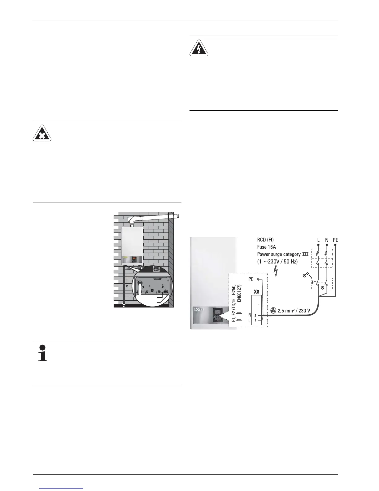
4.7 Electrical connection
All control and safety systems of the ROTEX GW are connected
and tested at the factory. Modifications on the electrical instal-
lation are dangerous and prohibited. The operator alone shall
bear responsibility for any resulting damage.
A flexible cable for the mains connection is already connected
inside the unit. Only the optional applications (e. g. outside
temperature sensor, room station, circulation pump)still need to
be connected to the controller.
Ɣ Check the supply voltage (~230 V, 50 Hz).
Ɣ Disconnect the junction box of the domestic installation.
Ɣ Connect a cable for mains connection via a main switch to be
provided by the customer and which isolates all the poles and
is still to be installed on the distribution box of the house
installation (isolating device in accordance with EN 60335-1).
Ensure that the polarity is correct.
Ɣ Restore power supply to the junction box of the domestic
electrical installation.
DANGER OF CHEMICAL BURNS!
The condensate coming from the burner contains acid
and can cause injury if it comes into contact with the
eyes or the skin.
Ɣ Wear protective clothing (safety glasses, rubber
gloves) when working on the condensate drain.
Ɣ If your skin comes in contact with anything, wash
the affected area immediately with tap water.
Ɣ If the chemicals come in contact with eyes,
immediately wash with tap water and consult an
ophthalmologist.
Ɣ Direct the condensate drain
hose (Ø 18/24 mm)
mounted on the condensate
siphon (fig. 4-13, item F) in
the factory with constant
gradient) and with free inlet
to the sewerage
connection.
The entire outlet must not
be capable of being locked
and must direct the conden-
sate safely and visibly to the
outside.
If necessary, the factory-fit-
ted corrugated hose can be
replaced by a suitable plas-
tic hose having a minimum
inside diameter of 13 mm.
Fig. 4-13 Connection of the
condensate drain
hose
The boiler can be drained if necessary via the hose
spigot leading out of the floor of the unit between the
heating return and the cold water connection (fig. 4-13,
item H).
Ɣ To do this, open the drain valve coupled to the hose
spigot (hexagon) by 1/2 a turn.