3 x Operation
BA ROTEX HPSU compact 4 - 03/2013
11
3 Operation
3.1 General 3.2 Display and operating elements
3.2.1 Display
All the operating steps are supported by appropriate displays in
the clear text display. Menu guiding is available in 6 different
languages (see section 3.3.1).
DANGER!
If electrical components come into contact with water,
this can cause an electric shock as well as cause
potentially fatal injuries and burns.
Ɣ Protect the displays and keys on the control
systems from the effects of moisture.
Ɣ To clean the display, use a dry cotton cloth.
Using aggressive cleaning agents and other
liquids can cause damage to equipment or lead
to an electric shock.
Maximum energy utilisation
The most effective energy utilisation is achieved by the
unit at the lowest possible return flow and hot water
temperatures. This requires, on the one hand,
hydraulic balancing of the heating system, which is
also frequently a requirement for conveting agents
and, on the other hand, that the setting of the hot water
preparation temperature is maximum 48 °C.
The safety settings of the HPSU compact hinder the
operation of the heat pump if
– the outdoor temperature is < 12 °C and simultane-
ously
– the storage tank temperature is < 30 °C.
Without backup heater:
At an outdoor temperature < 12 °C, the storage tank
water needs to be heated up by an external heater to
> 30 °C.
With backup heater (BUH):
At an outdoor temperature < 12 °C, the backup heater
(BUH) switches on automatically to heat the water in
the storage tank to > 30 °C.
Ɣ In order to accelerate the heating up process with
BUH, temporarily set the
– Parameter [T-DHW 1 des] > 55 °C,
– Parameter [Function Heating Rod] = "1" and
– Parameter [BOH power] = 9000 W.
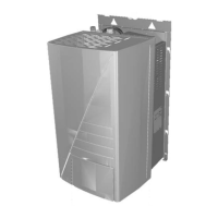
1 Clear text display
2 Setting: Configuration
3 Not assigned
4 Rotary switch
5 Setting: Info
6 Setting: Operating Mode
7 Setting: Set Temp Day
8 Setting: Set Temp Night
9 Setting: DHW Set Temp
10 Rotary button
11 Setting: DHW Installation
12 Setting: Time Programme
13 Operating button
Fig. 3-1 Arrangement of display and operating elements
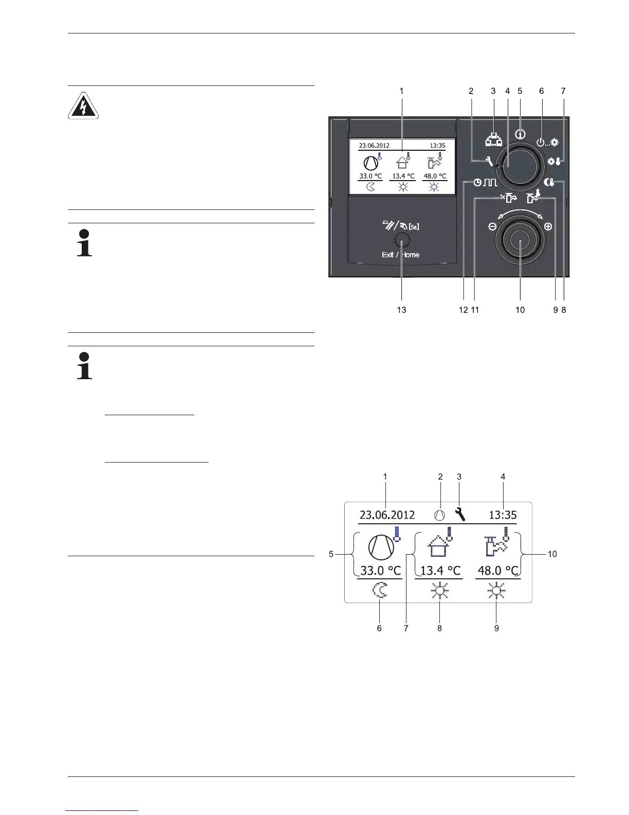
1 Date display
2 Status of refrigerant
compressor
3 Display of expert login
4 Display time
5 Current flow temperature
(heating circuit)
6 Status heating circuit
7 Current outdoor temperature
8 Active heating programme
9 Status of hot water genera-
tion
10 Current storage tank temper-
ature
Fig. 3-2 Controller display
 Loading...