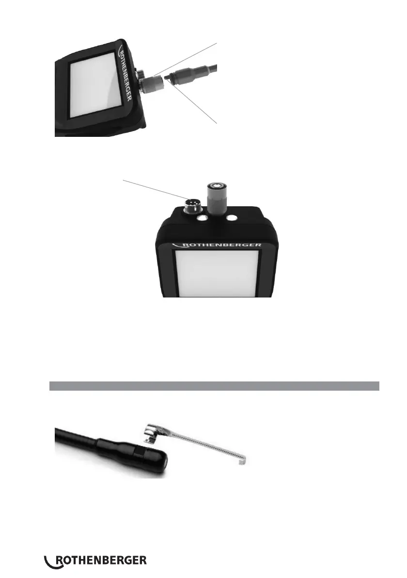
Slot
Key
Figure 6 - Cable Connections (Connector Style “A”, Black 9-Pin Style Connector)
(For use with standard Imager provided with i2000 and with Module 25/16 Imager)
Connector Style „B“
Figure 7 – Cable Connections (Connector Style “B”, Silver 5-Pin Style Connector)
(Connector Style “B” is used to attach previous versions of ROSCOPE Imager Cable to the
ROSCOPE i2000)
NOTE: 1.2 m (4’) cable extensions are available, for Connector Style
“A”
imager only, to increase
the length of your cable up to 9.7 m (32’) in length. To install an extension, first remove the
imager cable from the handheld device by loosening the knurled nut. Connect the extension(s)
to the handheld device as described above (Figure 6). The keyed end of the imager head cable
connects to the slotted end of the extension.
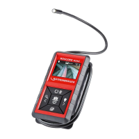
3.5 Installing the Camera Accessories
(Figure No. 8) shows a mirror, hook and magnet (accessories sold separately). Each accessory
attaches to the (provided) Connector Style
“A”
Imager Head the same way.
Figure 8 – Connector Style
“A”
accessories (sold separately)
To attach an accessory, hold the imager head as shown in (Figure No. 8). Slip the semicircle end of
the accessory over the flats of the imager head as shown in Figure 8. Then rotate the accessory a
1/4 turn so the long arm of the accessory is extending out as shown (Figure No. 9).