A4 US
US
A4
US
A4
A4 US
7
Redefining Flow Control
Please follow the instructions in section 3 for mounting the RHS
before attempting to cable up the unit.
4.1 Once the cable specification has been selected, cut to
the appropriate length (leaving approx. 200 mm at
each end for final termination).
4.2 Feed the cable to both the IQ3 and RHS terminal
compartments and secure the glands to ensure
watertight integrity is maintained.
4.3 Strip back the insulation and braiding so that the inner
twisted pair cores are exposed and fit AMP type ring
terminal crimps to each wire and shield braid. Insulate
the braid to prevent short circuits.
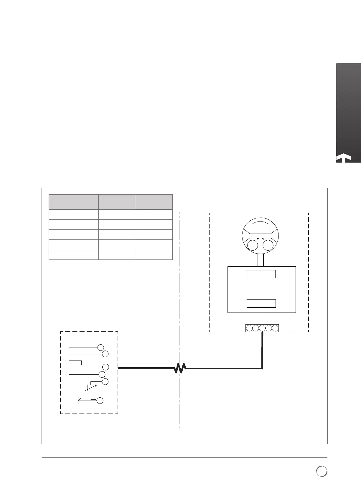
4.4 Connect the terminals in each compartment to the
correct terminal number by following the wiring
diagram supplied.
4 - Electrical Connections
20
32
24V (V-CUST)
CAN H
40
CAN SHIELD
CAN L
21
GND
Terminal
Block
SK2
RHS Bridge Board
SK1
18 WAY
50%
CLOSE
OPEN
STOP
REMOTE
LOCAL
1 2
3
4 5
47
E
Actuator
Remote Hand Station
ACTUATOR
TERMINAL BUNG NO.
RHS TERMINAL
BLOCK NO.
FUNCTION
20 1
24 V (V-CUST)
21 2 GND
32 3 CAN H
40 4 CAN L
47 5 SHIELD
Earth Ground Connection
A dedicated external earth point is provided for the attachment
of a protective earth cable.
This wiring diagram is for reference only, please refer to the specific actuator wiring diagram supplied with the unit.