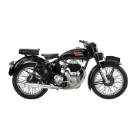
Do you have a question about the Royal Enfield 350 BULLET 1949 and is the answer not in the manual?
Engine configuration, lubrication, and crankshaft details.
Cylinder head material, cooling, and valve insert specifications.
Cylinder bore and stroke details for 350/500cc models.
Piston material, rings, and compression ratio information.
Connecting rod material and little end bearing specifications.
Crankcase construction and split details.
Crankshaft and flywheel assembly description.
Types of main bearings on driving and timing sides.
Cam material, hardening, and bush specifications.
Inlet and exhaust valve material details.
Valve operation via tappets, push rods, and rockers.
Timing drive mechanism and magdyno drive description.
Source of ignition and lighting system power.
Reference to specific carburetter sections F1 and F2.
Air filter type and functional description.
Explanation of the dry-sump lubrication system.
Details on breather function and types.
Description of gearbox, speeds, and gear changes.
Comparison of 350 and 500 Bullet clutch models.
Procedure for removing and refitting the timing cover.
Instructions for setting valve timing at a specific clearance.
How to adjust tappets, including cold clearance.
Step-by-step guide to removing the engine from the frame.
Procedure for removing the gearbox.
Steps for separating the crankcase halves.
Instructions for removing and replacing main bearings.
Procedure for removing and replacing cam and idler spindles.
Refers to engine removal sections for gearbox removal.
Steps for dismantling the gearbox.
Diagram showing carburetter with pilot jet system.
Illustrates two designs of Amal carburetters.
Overview of the Amal Monobloc Carburetter features.
Instructions for tuning the Monobloc carburetter.
General description of the Lucas Magdyno.
Maintenance schedule for the Magdyno.
General description of the Lucas Dynamo.
Lubrication requirements for the dynamo.
Inspection procedure for commutator and brush gear.
Technical test data for the dynamo.
Troubleshooting steps for charging circuit faults.
General description of the Control Box.
Specifies cut-in and drop-off voltages for the cut-out.
Procedure for servicing the control box and regulator.
General information about the PUZ7E battery.
Instructions for preparing the battery with electrolyte.
Routine checks and maintenance for the battery.
Servicing procedures for a discharged battery.
Description of the headlamp unit and its features.
Details the Lucas Light Unit construction.
Steps for replacing the light unit and bulb.
Information on parking light bulb mounting.
Describes earlier and later tail light types.
Describes frame construction and differences.
Details steering head races and their fitting.
Procedure for removing rear suspension units.
Servicing instructions for proprietary and Royal Enfield rear suspension units.
Description of the telescopic front fork.
Explains the fork's movement and damping system.
Steps for dismantling the fork for part replacement.
Description of the front fork with facia panel.
Explains the fork's operation and damping.
Steps for dismantling the fork for component replacement.
Describes the front fork with steel bottom tubes.
Instructions for dismantling the fork for parts replacement.
Details the front fork spring length and replacement criteria.
Information on steering head races and adjustment.
Steps for removing the front wheel from the fork.
Procedure for removing brake cover plate assemblies.
Steps for removing brake shoes and springs.
Information on replacing brake linings.
Procedure for removing the hub spindle and bearings.
Details the types and specifications of hub bearings.
Fitting tolerances and considerations for hub bearings.
Instructions for refitting ball bearings.
Steps for removing the front wheel from the fork.
Procedure for removing the brake cover plate assembly.
Steps for brake shoe replacement and lining fitting.
Information on fitting new brake linings.
Procedure for removing hub spindle and bearings.
Details hub bearing types and specifications.
Fitting tolerances for hub bearings.
Instructions for refitting ball bearings.
Description of the detachable rear wheel.
Procedure for removing the main portion of the rear wheel.
Steps for removing the complete rear wheel for brake access.
Description of non-detachable rear wheels.
Procedure for removing the rear wheel.
Steps for brake shoe replacement and lining fitting.
Information on fitting new brake linings.
Procedure for removing hub spindle and bearings.
Details hub bearing types and specifications.
Fitting tolerances for hub bearings.
Instructions for refitting ball bearings.
Tool for extracting the Magdyno pinion.
Tool for compressing valve springs.
Mandrels for valve guide operations.
Tool for extracting gudgeon pins.
Tool used for valve grinding.
Tool for lapping pump discs.
Spanner for the pump worm shaft.
Tool for extracting tappet guides.
Tool for extracting the clutch centre.
Tool for extracting crankshafts.
Tool for timing side roller race assembly.
Tool for driving side bearing assembly.
Plate for locating cam spindle assemblies.
Jig for 350 Bullet crankshaft.
Jig for 500 Bullet crankshaft.
Tool for expanding frames.
Grips for gland nuts.
Spanner for lockrings.
Hand grips for gland nuts.
Hand grips for outer tubes.
| Brand | Royal Enfield |
|---|---|
| Model | 350 BULLET 1949 |
| Category | Motorcycle |
| Language | English |