EasyManua.ls Logo

Royal Enfield 350 BULLET 1950 User Manual

Royal Enfield 350 BULLET 1950
102 pages
To Next Page IconTo Next Page
Page #1 background imageLoading...
Page #1 background image
ROYAL ENFIELD WORKSHOP MANUAL
WORKSHOP
MAINTENANCE MANUAL
FOR THE
Royal
Enfield
350 BULLET 194955
500 BULLET 195355
MAN 8
www.hitchcocksmotorcycles.com

Table of Contents

Question and Answer IconNeed help?

Do you have a question about the Royal Enfield 350 BULLET 1950 and is the answer not in the manual?

Royal Enfield 350 BULLET 1950 Specifications

General IconGeneral
BrandRoyal Enfield
Model350 BULLET 1950
CategoryMotorcycle
LanguageEnglish

Summary

SECTION A2a Technical Data

Valve Timing with .012 in. clearance

Valve timing specifications at 0.012 inch clearance.

SECTION A2b Technical Data

Valve Timing with 012 in. clearance

Valve timing specifications at 0.012 inch clearance.

SECTION B2 Engine Specification

1. Engine

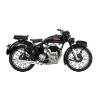
General description of the engine's configuration and features.

SECTION B2 Engine Specification (Continued)

16. Lubrication System

Details of the dry-sump lubrication system.

14. Carburetter

Carburetter types for 350cc and 500cc engines.

18. Gearbox

Description of the gearbox, speeds, and ratios.

19. Clutch

Details on the clutch mechanism for 350 and 500 Bullet models.

SECTION C2 Service Operations with Engine in Frame

1. Removal of the Timing Cover

Procedure for removing and refitting the timing cover.

2. Valve Timing

Instructions for setting the valve timing correctly.

3. Tappet Adjustment

Steps for adjusting the tappet clearances.

SECTION C2 Service Operations with Engine in Frame (Continued)

4. Ignition Timing

Procedure for setting the ignition timing.

12. Decarbonising

Process for decarbonising the engine components.

16. Overhaul of Oil Pumps

Procedure for overhauling the oil pumps.

26. Removal of the Magdyno

Procedure for removing the Magdyno unit.

6. Removal of the Cylinder Head

Procedure for removing the cylinder head.

14. Reassembly after Decarbonising

Steps for reassembling engine components after decarbonising.

10. Removal of the Cylinder Barrel

Procedure for removing the cylinder barrel.

19. Primary Chain Adjustment

How to adjust the primary chain tension.

23. Removal of the Clutch

Procedure for removing the clutch assembly.

11. Removal of the Piston

Steps to remove the piston from the cylinder.

SECTION D2 Service Operations with Engine Removed

1. Removal of the Engine from the Frame

Steps to remove the engine from the motorcycle frame.

2. Removal of the Gear Box

Procedure for removing the gearbox.

3. Dismantling the Crankcase

Steps to dismantle the crankcase halves.

SECTION D2 Service Operations with Engine Removed (Continued)

7. Reassembly of the Crankcase

Instructions for reassembling the crankcase halves.

SECTION E1 Gearbox and Clutch

1. Removal of Gearbox

Instructions for gearbox removal.

2. To Dismantle the Gearbox

Steps to dismantle the gearbox assembly.

SECTION E1 Gearbox and Clutch (Continued)

5. Re-Assembling the Gearbox

Steps for reassembling the gearbox.

6. Dismantling and Re-assembly of the Clutch

Procedure for clutch disassembly and reassembly.

SECTION F1 AMAL NEEDLE TYPE CARBURETTER

CARBURETTER WITH PILOT JET SYSTEM

Description of carburetters with pilot jet systems.

AMAL NEEDLE TYPE CARBURETTER

Table of specifications for Amal needle type carburetters.

SECTION F1 AMAL NEEDLE TYPE CARBURETTER (Continued)

HOW IT WORKS AND PART NAMES

Explanation of carburetter operation and identification of parts.

TUNING TWIN CARBURETTERS WITH SMALL NEEDLE JET

Instructions for tuning twin carburetters.

HOW TO TRACE FAULTS

Troubleshooting guide for carburetter faults.

SEQUENCE OF TUNING

Steps for tuning the carburetter.

Amal Monobloc Carburetter

1. General Description

General description of the Amal Monobloc carburetter.

2. Tuning the Carburetter(s)

Instructions for tuning the Amal Monobloc carburetter.

Amal Monobloc Carburetter (Continued)

3. Dismantling Carburetter

Steps to dismantle the Amal Monobloc carburetter.

4. Causes of High Petrol Consumption

Reasons for high petrol consumption and solutions.

SECTION G1c Lucas Magdyno

SECTION G1c Lucas Magdyno (Continued)

3. Testing Magdyno in Position on Engine

Procedure for testing the Magdyno on the engine.

SECTION G2b Lucas Dynamo Model E3LM

4 (a). Testing in Position to Locate Fault in Charging Circuit

Troubleshooting faults in the charging circuit.

SECTION G2b Lucas Dynamo Model E3LM (Continued)

4 (b). To Dismantle

Procedure to dismantle the dynamo.

4 (g). Reassembly

Dynamo reassembly procedure.

SECTION G3a Control Box

(a) Checking the wiring between battery and regulator

Checking wiring connections between battery and regulator.

(b) Checking the electrical setting of the regulator

Checking the regulator's electrical settings.

SECTION G3a Control Box (Continued)

(e) Adjusting the electrical setting of the regulator

Adjusting the electrical setting of the regulator.

(d) Checking the electrical setting of the cut-out

Checking the electrical setting of the cut-out.

(e) Adjusting the electrical setting of the cut-out

Adjusting the electrical setting of the cut-out.

SECTION G4a Battery Model PUZ7E

1. General

General description of the PUZ7E battery.

2. Preparation for Service

Steps for preparing the battery for service.

SECTION G4a Battery Model PUZ7E (Continued)

SECTION G5a Head and Tail Lamps

SECTION G5a Head and Tail Lamps (Continued)

SECTION H1 FRAME

EXPLODED VIEW OF LATE 1954-1955 350 BULLET AND 500 BULLET FRAME

Exploded view of the frame for 1954-1955 models.

1. Description of Frame

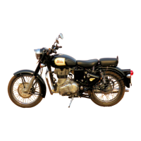
General description of the frame construction.

3. Removal of Rear Suspension Unit

Steps to remove the rear suspension unit.

SECTION H1 FRAME (Continued)

7. Wheel Alignment

Instructions for checking and adjusting wheel alignment.

SECTION J1 Front Fork

With Casquette and Aluminium Alloy Bottom Tubes

Description of front fork with casquette and alloy bottom tubes.

2. Operation of the Fork

Explanation of how the front fork operates.

SECTION J1 Front Fork (Continued)

7. Removal of Complete Fork

Steps to remove the complete front fork assembly.

SECTION J3 Front Fork

With Facia Panel and Aluminium Alloy Bottom Tubes

Description of front fork with facia panel and alloy bottom tubes.

2. Operation of Fork

Explanation of the front fork operation.

SECTION J3 Front Fork (Continued)

3. Dismantling the Fork to Replace Spring, Oil Seal or Bearing Bushes

Procedure to dismantle the fork for part replacement.

7. Removal of Main Tubes

Steps to remove the fork main tubes.

6. Removal of Facia Panel Fork Head, Spring, etc.

Steps to remove fork head, spring, and related parts.

SECTION J4 Front Fork

With Facia Panel and Steel Bottom Tubes

Description of front fork with facia panel and steel bottom tubes.

2. Dismantling Fork to Replace Spring, Oil Seal or Bearing Bushes

Procedure to dismantle fork for part replacement.

SECTION J4 Front Fork (Continued)

5. Removal of Facia Panel Fork Head, Spring, etc.

Steps to remove fork head, spring, and related parts.

6. Removal of Main Tubes

Steps to remove the fork main tubes.

SECTION K1 Front Wheel With Dual 6 in. Brake

2. Removal of Brake Cover Plate Assemblies

Procedure to remove brake cover plate assemblies.

SECTION K1 Front Wheel With Dual 6 in. Brake (Continued)

SECTION K2 Front Wheel With Single 6 in. Brake

1. Removal from Fork

Steps to remove the front wheel from the fork.

3. Removal of Brake Shoes and Springs

Steps to remove brake shoes and springs.

SECTION K2 Front Wheel With Single 6 in. Brake (Continued)

SECTION L1 Rear Wheel (Detachable Type)

SECTION L1 Rear Wheel (Detachable Type) (Continued)

SECTION L2 Rear Wheel (Non-Detachable Type)

1. Description

General description of the non-detachable rear wheel.

SECTION L2 Rear Wheel (Non-Detachable Type) (Continued)

5. Removal of Hub Spindle and Bearings

Steps to remove hub spindle and bearings.

SECTION M2 Special Tools

Related product manuals