
C
Christopher LopezJul 30, 2025
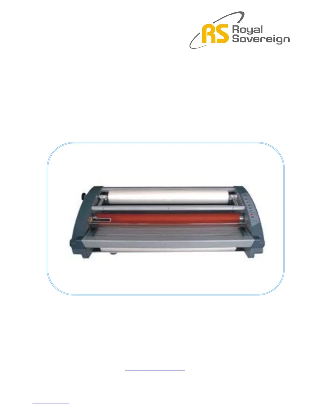
What to do if Royal Sovereign Laminator rollers are not running?
- MMatthew MerrittJul 30, 2025
If the rollers on your Royal Sovereign laminator aren't running, there could be several reasons: * Ensure the safety cover is correctly positioned so that its edge presses the micro switch lever completely. * Check that the motor wire connectors are properly connected. * If film is jammed, press the reverse button and gently pull the film backward. If it jams again, stop reversing, press the run button, and continue pulling the film backward. * A defective main motor may be the cause. In this case, replace the motor. * A defective Main PCB may be the cause. In this case, replace the Main PCB only when all of the above mentioned Emergency switch, Frame paper guide, Safety cover switch, motor wire connectors, main motor and film are normal.