2 3
Profeesional LCR Meter / EnglishProfeesional LCR Meter / English
3.Functional Description
3-1 Introduction
The LCR meter could measure Inductance/Capacitance/ Resistance with secondary parameters including
dissipation factor (D), quality factor(Q), phase angle(
θ
), equivalent series/parallel resistance(ESR or Rp).
The meter is fully auto ranging operation for AC impedance & DC resistance measurement. It means the
user could measure the L/C/R components directly at AUTOLCR smart mode without changing the function
key. User could also select the target test frequencies of 100Hz/120Hz/1kHz/10kHz /100kHz depending on
DUT(device under test) type. Components could be measured in series or parallel mode according to the
DUT impedance automatically.
3-2 Features
• Dual LCD display
• Auto LCR smart check and measurement
• Series/Parallel modes are selectable
• Ls/Lp/Cs/Cp with D/Q/
θ
/ESR parameters
• Support DCR mode 200.00Ω~200.0MΩ
• Five different test frequency are available: 100/120/1k/10k/100k Hz
• Test AC signal level: 0.6mVRMS typ.
• Test range: (ex. F=1kHz)
L: 200.00 μH ~ 2000.0 H
C: 2000.0 pF ~ 2.000 mF
R: 20.000 Ω ~ 200.0 MΩ
• Multi-level battery voltage detector
• Support Backlight & Buzzer sound driver
• Primary Parameters Display:
DCR:DC Resistance
Ls:Serial Inductance
Lp:Parallel Inductance
Cs:Serial Capacitance
Cp:Parallel Capacitance
Rs:Serial Resistance
Rp:Parallel Resistance
• Second Parameter Display:
θ
: Phase Angle
ESR:Equivalence Serial Resistance
D:Dissipation Factor
Q:Quality Factor
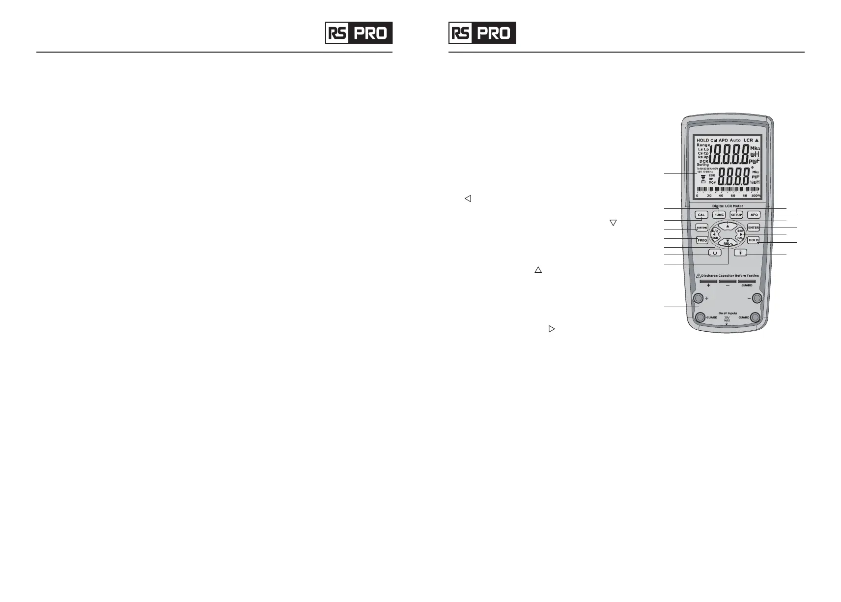
4.Front Panel Overview
1
2 9
10
11
13
15
16
14
12
3
4
5
7
8
6
4-1 Front Panel Display Descriptions
1. LCD Display
2. Mode (Auto LCR / L / C / ACR / DCR) selection button
3. Calibration mode selection button
4. Sorting mode button
5. Secondary Display mode (for dissipation factor(D),
quality factor (Q), phase angle (
θ
), equivalent series
resistance (ESR),equivalent parallel resistance(Rp)
measurement) selection and the modify sorting value
(
) button
6. Test Frequency selection button
7. Relative mode and the modify sorting value ( ) button
8. Power ON/OFF button
9. Enter modify sorting value mode button
10. APO (Auto power off) button
11. Modify sorting value ( ) button
12. Confirm and select the value user need to modify in
sorting mode
13. Hold Display mode button
14. Parallel or Series measurement method selection and
the modify sorting value ( ) button
15. Back light button
16. Input sockets (banana jack inputs) and terminals for
positive, negative, and guard (see “Guard Terminal” in
“SUPPLEMENTAL INFORMATION” section for details)
5.Powering Instrument
Before beginning to operate the instrument, a power source is necessary for it to turn on. Installing Battery
5-1 Installing Battery
The LCR meter use battery to provide power to the instrument so that it can be portable. It use six standard
1.5V size batteries.
• Place the meter upside down. Open up the back-flip stand, and locate the screw that tightens the
battery compartment cover.
• Use a screwdriver to unscrew and remove the cover.
• Insert six 1.5V batteries into compartment. Note the positive (+) and negative (—) terminals as indicated
inside the battery
• compartment. Be sure to insert the battery with matching polarity.
 Loading...