CHAPTER 3 | INSTALLATION AND OPERATION
CONNECTING AUDIO SOURCES CONTINUED
AD-8
CP-1650
Speaker Pair
Zone 1
Speaker Pair
Zone 2
Speaker Zone 1 Speaker Zone 1 Speaker Zone 2
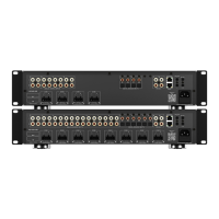
The following diagram shows just one of many possible congurations
when a CP-1650 in Bridge Mode is connected to an RTI audio distribution
system (the AD-8 audio distribution system is shown here). In this
example, CH 1/2 and CH 3/4 on the rear of the CP-1650 have been daisy
chained so that their output goes to different individual speakers with the
same audio feed. CH 5/6 goes to a separate, individual speaker with a
separate audio feed. The channel level adjusters on the rear of the CP-
1650 can increase or decrease the attenuation level going to each speaker
pair independently.
Note: in the Bridge Mode, only the input level controls of L,
(Left) CHANNELS are operative.
Note: do not use 4 ohm speakers in Bridge Mode.