Einbau- und Betriebsanleitung
Installation and Operating instructions
Instructions de montage et de service
5112-8010
10/2012
3 Komponenten /components
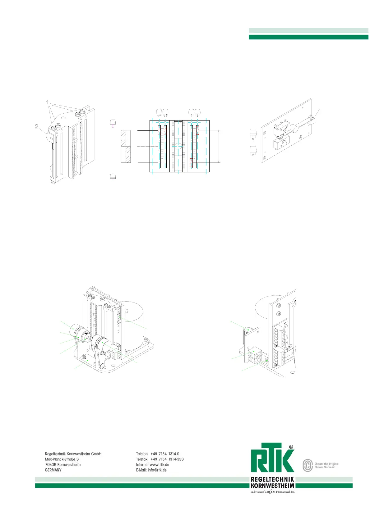
Einstellung Wegabschaltung
stroke adjustment
contacteur de course
Kraftabschaltung
force switch
contacteuer de force
Bild 2
Schalthebel
shift lever
levier de commande
Bild 3
1 Einstellspindel (Hub) / adjusting spindle (stroke) /
tige de justage
2 Schaltnocke / camswitch / cames de commutation
chtung: E1 und E2 nicht über Schaltpunkt
bewegen
Attention: Don’t move E1 and E2 over the
Switch point
Attention: Ne pas bouyer E1 et E2 au dersus
Du point de commutation
Potentiometer
potentiometer
potentiomêtre
Heizwiderstand
heating resistor
résistance de chauffage
POT 2
POT 1
1
2
3
4
5
Bild 4
1
2
3
Bild 5
1 Potentiometerhalter / potentiometer lever / potentiomêtre levier
2 Einstellring / adjusting ring / anneau de justage
3 Ritzel / gear / roue denteé
4 Montagewinkel / assembly plate / plaque de montage
5 Leiterplatte mit Klemmleiste / p.c.b. with terminal strips / plaque
conductrice avec plaque á borne
1
Heizwiderstand / heating resistor / résistance de
chauffage
2 Klemmleiste / terminal strips / plaque á borne
3 Befestigungsschraube / screw / fileté
E4
E3 E2E1
H
u
b
m
a
x
.
s
t
r
o
k
e
m
a
x
.
c
o
u
r
s
e
m
a
x
.
Spindel ausgefahren
Spindel eingefahren
on
on
off
off
F1 F2 F3
F4 F6F5
spindle extended
tige sortie
spindle inserted
tige rentrée