10
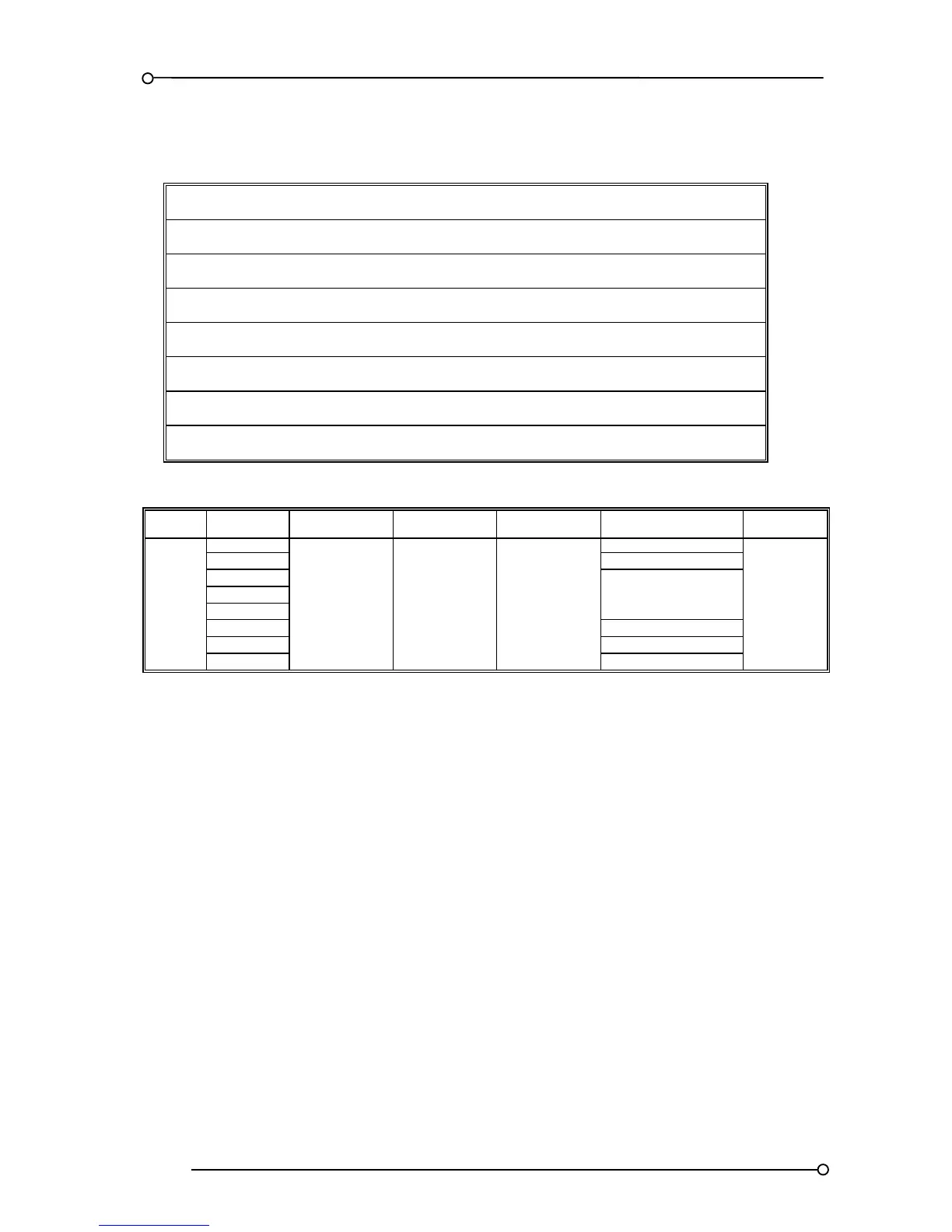
Model Number Description
UC625 = Model no prefix
** = Number of available alarm channels [Not including the 2 power failure alarms]
** = LED colour RD = Red (Standard)
H = Input supply 1 universal (88-360VDC or 88-265VAC)
** = Input supply 2 specify option H or L
024D = 24VDC signal supply voltage OR
Options for 48/110/250VAC/DC signal supply inputs
R = Individual channel signal duplicating relays fitted
MODEL
Typical Model No
UC625 40 RD H H 024D R – M*
M* Option code see below)
Please note:- If more than 40 ways are required as a single system expansion UC625 units can be
connected via the expansion ribbon bus connector as detailed later in the manual on all units shipped
after August 2004
Option Codes
These Codes are added as a suffix to the Model No and MUST be specified at the time of ordering.
M1 = Horn disabled on System Test
M2 = Modified Ringback sequence, disabled ring back audible and lamp test in place of system test.
M3 = ISA R12 Ringback sequence, disabled Ringback horn, lamp test in place of system test and
response time changed to 5mS trip 5S pre-alarm.
M4 = ISA R12 Ringback sequence, disabled ring back audible, lamp test in place of system test,
response time changed to 5mS trip and 5S pre-alarm and combined Lamp / Audible Test
pushbutton function.