EasyManuals Logo

RTK UC625 series User Manual

RTK UC625 series
59 pages
To Next Page IconTo Next Page
To Previous Page IconTo Previous Page
Page #40 background imageLoading...
Page #40 background image
40
Identifying Card Types
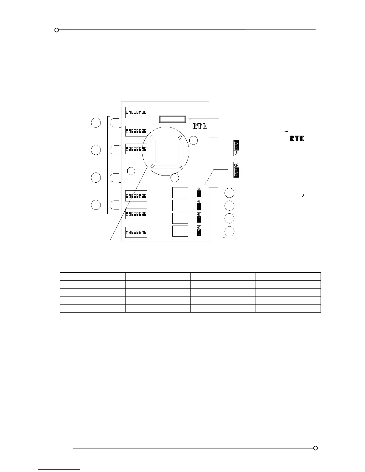
The Applications Specific Integrated Circuit (ASIC) used on the UC625 annunciator
varies depending on the options specified at the time of order
ALARM CARD
CB5303POP*
C17
RL1
RL2
RL3
RL4
CHANNEL
SW4
AS5317-*
ASIC
SW1
3
SW3
1 2 54 6 87
NO
NORMALLY OPEN
NO
NORMALLY CLOSED
NC
NC
NO
NO
NC
NO
NC
NC
CONTACT SET
NO
NC
C16
FCV = 24VDC SET FOR 24VDC
SUPPLY VOLTAGE
LK1
LK2
LK3
LK4
LK4
1
2
3
4
1
2
3
4
CHANNEL
SW6
SW2
SW5
ON
8
1 2 3 4
ON
5 6 7
81 2 3 4
ON
5 6 7
8
ON
1 2 43 65 7
821 43
ON
65 7
81 2 43 65 7
ON
The following ASIC versions are used in UC625 models
Version
Alarm Card ASIC
SPR Card ASIC
SPR ETN ASIC
Standard
AS5317
AS5378
AS6521
M2
AS6247
AS6250
AS6522
M3
AS6454
AS6250
AS6522
M4
AS6454
AS7827
AS6522
The optional functions are defined below
M2 = Modified Ringback sequence, disabled ring back audible and lamp test in place of system test.
M3 = ISA R12 Ringback sequence, disabled Ringback horn, lamp test in place of system test and
response time changed to 5mS trip 5S pre-alarm.
M4 = ISA R12 Ringback sequence, disabled ring back audible, lamp test in place of system test,
response time changed to 5mS trip and 5S pre-alarm and combined Lamp / Audible Test
pushbutton function.

Table of Contents

Questions and Answers:

Question and Answer IconNeed help?

Do you have a question about the RTK UC625 series and is the answer not in the manual?

RTK UC625 series Specifications

General IconGeneral
BrandRTK
ModelUC625 series
CategorySecurity System
LanguageEnglish

Related product manuals