44
Alarm Card Relay And Horn Settings (Set In Pairs)
Switch SW4 and SW6 are used to control the operation of the individual channel repeat relays, group
relays and audible alarms
SW4 controls channel 1 & 2, SW6 controls channel 3 & 4
SWITCH STATE FUNCTION
SW*-S1
ON REPEAT RELAYS FOLLOW THE SIGNAL INPUT
OFF REPEAT RELAYS FOLLOW THE ALARM LOGIC
SW*-S2
ON NORMALLY DE ENERGISED REPEAT RELAYS
OFF NORMALLY ENERGISED REPEAT RELAYS
SW*-S3
ON ENABLE GROUP RELAY OUTPUT
OFF DISABLE GROUP RELAY OUTPUT
SW*-S4
ON GROUP RELAY SIGNAL FOLLOWS INPUT
OFF GROUP RELAY FOLLOWS ALARM LOGIC
SW*-S5
ON REFLASH SIGNAL TO GROUP RELAY
OFF DISABLE REFLASH SIGNAL TO GROUP RELAY
SW*-S6
ON SYSTEM TEST WILL NOT OPERATE REPEAT RELAYS
OFF SYSTEM TEST WILL OPERATE REPEAT RELAYS
SW*-S7
ON AUDIBLE SIGNAL TO HNA RELAY & AUDIBLE 1
OFF DISABLE AUDIBLE SIGNAL TO HNA RELAY & AUDIBLE 1
SW*-S8
ON AUDIBLE SIGNAL TO HNB RELAY & AUDIBLE 2
OFF DISABLE AUDIBLE SIGNAL TO HNB RELAY & AUDIBLE 2
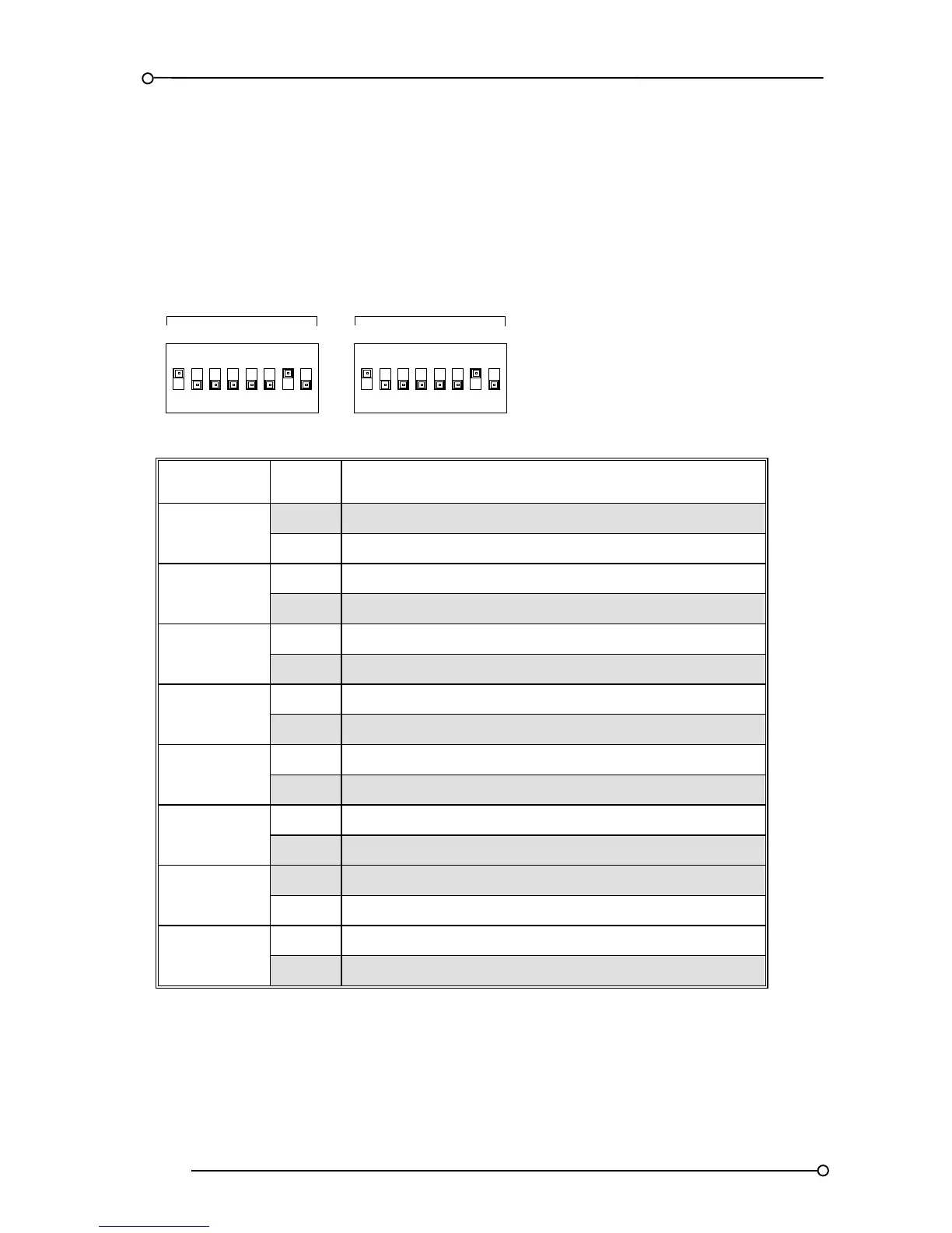
* = Switch SW4 is used to adjust channel 1 & 2 or SW6 is used to adjust channel 3 & 4 as required
Figure 12. Alarm Card DIL Switch details (SW4 and SW6)