Do you have a question about the RTS KP-32 and is the answer not in the manual?
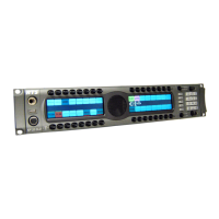
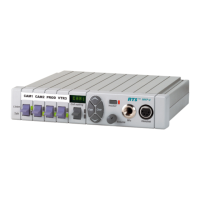
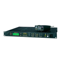
Details the KP-32 keypanel and related expansion and control panels.
Provides additional intercom keys for expanded system capacity.
Allows adjustment of listen levels for individual intercom keys.
Information regarding product ownership and copyright restrictions.
Details on obtaining warranty and service support for RTS products.
Contact information for technical assistance and customer support.
General disclaimers and safety precautions for product usage.
Overview of the KP-32's design, capabilities, and advanced features.
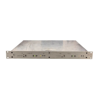
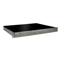
Details on available options like Connector Module, CSI-100, EKP-32, and LCP-32.
Guidelines for installing the equipment safely and effectively in a rack.
Configuration options using DIP switches for keypanel behavior.
Procedures for setting the keypanel's address for system identification.
Instructions for connecting various modules and cables to the keypanel.
Detailed overview of the KP-32's physical and functional characteristics.
Description of the Connector Module and its provided ports.
Guidance on environmental and mechanical aspects of rack installation.
Configuration for footswitch input on the Connector Module.
Setting the keypanel operation mode (Mode 1 or Mode 2).
Switches reserved for testing and debugging purposes.
How the KP-32 is identified by address switches in intercom systems.
Procedure for setting the address for the Zeus intercom system.
Procedure for setting the address for the ADAM CS system.
Connecting expansion panels and level control panels.
Using frame connectors to interface with the intercom system.
Details on power input and headset connectors.
Adjusting gain for headset and panel microphones.
How the screen saver functions and is enabled/disabled.
Switching between headset and speaker output.
How to adjust listen volume for different sources.
Interpreting text displayed on the intercom keys.
Understanding the different states of the talk LEDs.
Indicates a busy state or priority conflict for IFB/remote destinations.
Signals an incoming call from a destination.
Indicates a latched key requiring external footswitch activation.
Shows when the listen function is active.
How to use keys for momentary and latching talk/listen.
Using keys with auto functions like Auto Follow, Auto Listen, etc.
Using keys with options like Group and Solo.
How talk keys affect speaker/headphone volume.
Assigning keys for Telephone Interface (TIF) operation.
How to mute the microphone using the MUTE key.
Managing incoming calls when no key is assigned.
How to answer incoming calls using the Telephone Interface.
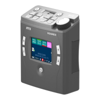
Using keypad sequences for phone calls with KP9X.
Step-by-step guide for manual dialing using KP9X.
How to redial the last dialed number using KP9X.
Overview of storing and dialing numbers with KP9X.
Procedure to save numbers in the TIF-951 unit.
Procedure to save numbers directly on the KP-32.
How to initiate a call using stored autodial numbers.
Step-by-step guide for manual dialing using the KP-32 menu.
Using the KP-32 menu to redial a previously called number.
Methods to view keypanel configuration details.
Using specific keypad sequences to request information.
Viewing panel ID, level 2 talk, and listen assignments.
Overview of methods for assigning intercom keys.
Assigning keys using numeric codes for ports and lines.
Copying an active call assignment to a key.
Duplicating an existing key assignment to another key.
Clearing a key assignment using the call waiting window.
Clearing a key assignment by copying a blank state.
Steps to navigate and access the keypanel's menu system.
Viewing different types of key assignments (P-P, PL, IFB, etc.).
Listing intercom ports currently active on the keypanel.
Viewing assignments for defined key groups.
Accessing other key assignments not currently visible.
Viewing talk level 2 assignments for keys.
Viewing all configured listen assignments.
Viewing matrix names for trunked systems.
Step-by-step guide to using the Key Assign menu.
Selecting a matrix for key assignment in trunked systems.
Assigning keys for Matrix, Point-to-Point, and Party Line destinations.
Assigning keys for IFB, Special List, and System Relay functions.
Assigning keys for Camera ISO and UPL Resource functions.
Configuring keys with auto functions like AutoFollow, AutoListen.
Modifying the listen gain levels for specific keys.
Restoring default listen levels for all assigned keys.
Modifying which setup page is assigned to key rows.
Storing and managing autodial numbers.
Adding chime tones for incoming call announcements.
Disabling chime tones for selected keys.
Creating and configuring key groups for simultaneous activation.
Removing existing key group configurations.
Assigning a key to turn off all others when activated.
Disabling the solo function for a key.
Enabling or disabling auxiliary audio input paths.
Accessing ports in trunked intercom systems.
Setting the communication baud rate for the system.
Enabling or disabling caller volume adjustments.
Adjusting audio level reduction when a talk key is active.
Adjusting alphanumeric display brightness levels.
Adding notch filters to audio sources.
Minimizing noise by gating audio sources.
Routing audio signals to different destinations.
Choosing between front panel or rear headset connectors.
Configuring KP-32 to skip LCP-32 usage for specific keys.
Mapping GPIO inputs to activate intercom keys.
Mapping GPIO inputs to activate key groups.
Clearing existing GPIO input assignments.
Managing GPI output assignments for keys.
Selecting between Normal and Hot Mic for matrix output.
Choosing between panel and headset microphones.
Setting the minimum available volume level.
Setting module ID numbers for key and display modules.
Adjusting the audio output level to the matrix.
Configuring audio routing to the preamp output.
Restoring all custom settings and autodial numbers.
Setting IP Address, Netmask, and Gateway for RVON devices.
Storing custom settings in non-volatile memory.
Configuring screen saver delay and display behavior.
Adjusting the level of own voice heard in headphones.
Testing key and display operations on the panel.
Technical details for the microphone preamplifier.
Technical details for the built-in tone generator.
Technical details for the headphone amplifier.
Technical details for the speaker amplifier and speaker.
Nominal and peak levels for intercom audio.
Input level details for program input.
Power supply, environmental, and approval ratings.
Pin configuration for the panel microphone jack.
Pin configuration for the headset connector.
Pin details for the power input connector.
Pinouts for DE9S and RJ12 intercom connectors.
Types for expansion and LCP connectors (RJ45).
Pinouts for auxiliary program audio inputs.
Pinouts for the first set of relay outputs.
Pinouts for the second set of relay outputs.
Pinouts for opto-isolated control inputs.
Pin configuration for OC 1 and 2 outputs.
Pin details for the external headset connector.
Pin configuration for foot switch and speaker connections.
Pin configuration for the unbalanced panel microphone input.
Pin configuration for the balanced microphone output.
List of FUNC DISPLAY commands for viewing keypanel info.
Names of display requests accessible via scrolling.
Quick steps for hanging up phone calls on KP9X.
Quick steps for dialing phone numbers on KP9X.
Quick steps for redialing numbers on KP9X.
Quick reference for KP9X autodial operations.
Summary of steps to access the KP-32 menu system.
Overview of available menus and their sub-items.
Details on switches affecting Mode 2 operation.
LED behavior for intercom keys in Mode 2.
Specific talk LED states and their meanings in Mode 2.
Display indication for busy or in-use status.
Indicates busy state or priority conflict for IFB/remote.
Signals an incoming call from a destination.
Indicates a latched key requiring external footswitch activation.
Explanation of the All Call key function.
Definition of user-changeable names for destinations.
Explanation of the Auto Follow listen key assignment.
Definition of special key assignments that work with others.
Explanation of the Auto Listen listen key assignment.
Explanation of the Auto Mute listen key assignment.
Explanation of the Auto Reciprocal listen key assignment.
Explanation of the Auto Table listen key assignment for IFBs.
Explanation of crosspoints in intercom system audio routing.
Definition of any point a talk key talks to or listen key listens to.
Explanation of Dim Table and speaker dimming features.
Explanation of General Purpose Input/Output controls.
Explanation of Interrupt Foldback communication.
Explanation of isolating intercom ports for private communication.
Definition of intercom system routing, often interchangeable with System.
Explanation of party lines for group communication.
Definition of connection points for devices and audio sources.
Explanation of Relay usage, similar to GPI output.
Explanation of special lists for group calls or zone paging.
Definition related to talk level 1 and talk level 2 assignments.
Definition of the normal talk key assignment.
Definition of the second talk assignment for stacked keys.
Explanation of interconnecting multiple intercom systems.
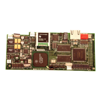
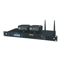
General description of the RVON-1 card's VoIP capabilities.
Key features including Ethernet connectivity and audio channel support.
Technical details for digital audio processing and codecs.
Pinout details for Ethernet and expansion connectors.
Detailed pinout for the 14-pin expansion connector.
List of default IP addresses for RVON devices.
Configuration options via DIP switches on the RVON-1.
Required firmware versions for system components.
Part numbers and guidance for replacing flash chips.
Accessing RVON setup through the service menu.
Procedure to set the IP address for the RVON-1 card.
Dynamically selecting RVON intercom connections.
Basics of network setup, LAN/WAN differences, and IP addressing.
Understanding the differences between Local and Wide Area Networks.
Explanation of LANs, nodes, and IP address routing.
How devices access networks across geographical areas.
How IP addresses are translated for WAN access.
Definition and use of network port numbers.
Steps to find the computer's IP address using ipconfig.
Verifying network reachability using the ping command.
Potential issues with network devices blocking connections.
Explanation of network bridges connecting LAN segments.
Explanation of DNS servers for translating domain names.
Explanation of gateways as network entrance points.
Explanation of network hubs as connection points.
Definition and format of Internet Protocol addresses.
Definition of Local Area Networks and their characteristics.
Definition of network ports as connection endpoints.
Definition of routers for forwarding data packets.
Definition of subnets and their use in network segmentation.
Explanation of network switches for filtering and forwarding packets.
Definition of Wide Area Networks connecting large geographical areas.
Methods for programming RVON cards via serial or telnet.
Steps to access the Telnet interface for RVON-1 configuration.
Commands to set IP address, netmask, and gateway.
Commands for serial settings, username, and password.
Command to set the Voice Activation Detection threshold.
Commands to set channel destination and audio codec.
Commands to adjust input and output gain for channels.
Commands to manage channel connection states (onhook/offhook).
| Brand | RTS |
|---|---|
| Model | KP-32 |
| Category | Intercom System |
| Language | English |