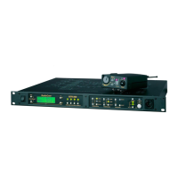
KP-32 User Manual Specifications 59
Bosch Security Systems, Inc.
User Manual
F.01U.193.253
Rev. 16
Relay 3 & 4 Out
Type: 9-pin male D-Sub
Pin-out:
Pin 1: NC contact 3
Pin 2: COM contact 3
Pin 3: NO contact 3
Pin 4: NC contact 4
Pin 5: COM contact 4
Pin 6: NO contact 4
Pin 7: +5 VDC
Pin 8: Ground
Pin 9: +5 VDC
NOTE: The relay 1 and 2 contacts are electrically separate, but operate in unison. The relay 3 and 4 contacts are
electrically separate, but operate in unison. The +5VDC pins are connected internally through 1K resistors to
+5VDC and can source 5mA. This voltage can be used with the relay contacts to create an active high output for
some devices that require a +5VDC signal to activate. For example, connecting pin 7 to pin 3 of the Relay 1&2
connector results in +5VDC on pin 2 when the relay is activated.
Opto 1-4 In (Opto-isolated control inputs)
Type: 9-pin male D-Sub
Pin-out:
Pin 1: Input 1 Gnd
Pin 2: Input 2 Gnd
Pin 3: Input 3 Gnd
Pin 4: Input 4 Gnd
Pin 5: Gnd
Pin 6: Switch contact input 1
Pin 7: Switch contact input 2
Pin 8: Switch contact input 3
Pin 9: Switch contact input 4
NOTE: A contact closure between any switch input and ground activates that input. The switch contact inputs are also
connected internally through 1K resistors to internal +5VDC and can source 5mA for use with an external
transistor switch circuit.
 Loading...