Copyright © 2016 Ruckus Wireless, Inc.
Published June 2016, Part Number 800-71267-001 Rev A
Page 3 of 4
STEP 3A: ATTACHING THE MOUNTING BRACKET TO A
F
LAT SURFACE
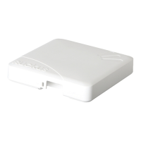
1 Place the mounting bracket at the location on the flat surface where you want to
mount the AP. Use the holes on the mounting bracket as a template to mark the
locations of the mounting holes.
Figure 6: Mounting bracket flat surface holes
2
Remove the mounting bracket from the flat surface.
3 Drill holes required for the mounting hardware.
NOTE: The hardware required for mounting to a wall are not included in the mounting kit.
4 Attach the mounting bracket to the flat surface using the mounting hardware.
5 Using the mounting hardware instructions, tighten the hardware to secure the
mounting bracket.
6 Continue with Step 4: Mounting the Linkage Bracket to the U-Joint Bracket.
STEP 3B: ATTACHING THE MOUNTING BRACKET TO A
M
ETAL POLE
1 Insert the open end of one steel clamp into the upper two slots on the mounting
bracket.
2 Take the other steel clamp and insert it into the lower two slots on the mounting
bracket.
NOTE: The clamps can be daisy-chained together to accommodate larger
poles.
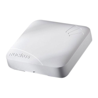
3 Use the clamps to attach the mounting bracket to the pole. Tighten the clamps to
3 N.m or 27 in-lbs, or per manufacturer’s specifications.
Figure 7: Attaching the mounting bracket to a vertical pole
4
Continue with Step 4: Mounting the Linkage Bracket to the U-Joint Bracket.
STEP 4: MOUNTING THE LINKAGE BRACKET TO THE
U-J
OINT BRACKET
The linkage bracket attaches to the U-joint bracket using an M8 bolt and washer set. The
linkage bracket is symmetrical, and either end can be attached to the U-joint bracket.
NOTE: Make sure that linkage bracket is installed with its serrated external-
tooth lock washer on the inside of the U-joint bracket flanges. This ensures
that the azimuth adjustment does not change.
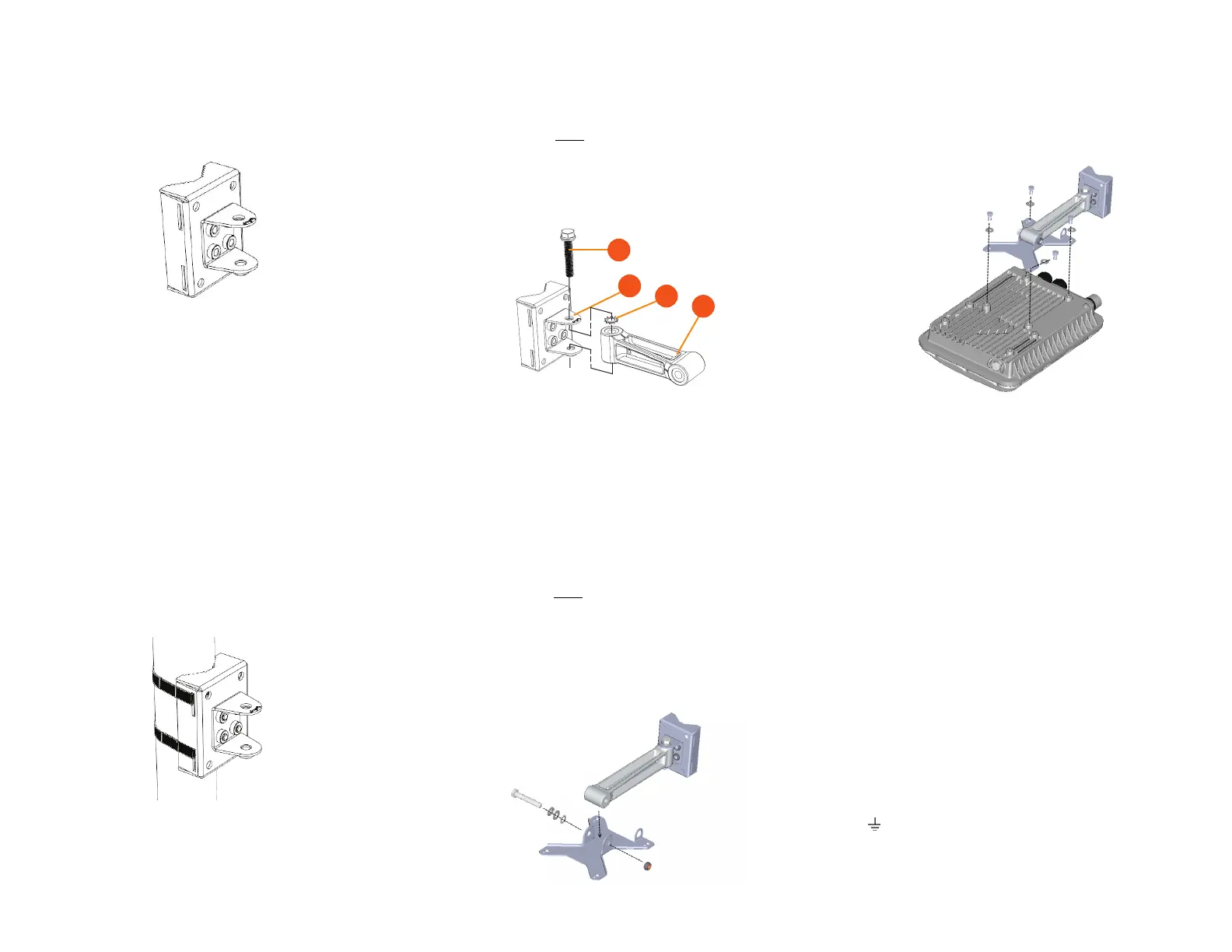
1 Loosely assemble the linkage bracket (A), the U-joint bracket (C), one serrated
external-tooth lock washer (B),
and one M8 bolt and washer set (D).
Figure 8: Attaching the linkage bracket to the U-joint bracket
2
Set the azimuth required by the AP.
3 Tighten the M8 bolt to 13.6 N-m (10 ft-lbs).
4 Continue with Step 5: Attach the AP bracket to the linkage bracket.
STEP 5: ATTACH THE AP BRACKET TO THE LINKAGE
BRACKET
Attach the AP bracket to the linkage bracket using the included bolt, nut, lock washer, flat
washer, serrated external-tooth washer shown in Figure 9.
The AP bracket attaches to the linkage bracket using an M8 bolt and washer set. The
linkage bracket is symmetrical, and either end can be attached to the AP bracket.
NOTE: Make sure that linkage bracket is installed with its serrated external-
tooth lock washer on the inside of the AP bracket flanges. This ensures that
the elevation adjustment does not change.
1 As described in Step 4: Mounting the Linkage Bracket to the U-Joint Bracket, loosely
assemble the AP bracket (shown in Figure 10), the linkage bracket (A in Figure 8), the
second serrated external-tooth lock washer (B in Figure 8), and the second M8 bolt
and washer set (D in Figure 8).
Figure 9: Attach the linkage bracket to the AP bracket
STEP 6: ATTACHING THE AP BRACKET TO THE
A
CCESS POINT
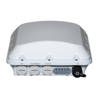
1 Place the AP bracket onto the back side of the AP so that the four larger screw holes
on the bracket align with the four screw holes on the AP. Make sure that the end of
the AP bracket with the hoisting loop is on the same side as the AP PoE IN port.
Figure 10: Attaching the AP bracket to the AP
2
Use four 0.5-inch x 0.250-28 hex bolts with split lock and flat washer sets to
mount the AP bracket to the AP. Tighten the bolts to 2.5-3.0 N.m or 22-27 in-lbs.
CAUTION: Make sure that the screws are no longer than 0.5 inch.
If a screw is longer than 0.5 inch, it can damage the AP chassis.
3 If required, suspend the AP by attaching a carabiner to the hoisting loop on the AP
bracket.
NOTE: This kit may include extra screws, nuts and washers. You may use
the extras wherever required.
4 Continue with Step 7: Set the Elevation and Tighten Elevation Bolt.
STEP 7: SET THE ELEVATION AND TIGHTEN ELEVA-
TION BOLT
1 Set the elevation required by the AP.
2 Tighten the M8 bolt to 13.6 N-m (10 ft-lbs).
3 Continue with Step 8: Powering the AP with AC.
STEP 8: POWERING THE AP WITH AC
1 Separate the AC cable connector parts by unscrewing the boot from the cable gland
and the cable gland from the connector housing.
2 Feed the end of the AC cable through the boot and cable gland.
3 Strip the AC cable as shown.
4 Insert the stripped part of the conductors into the appropriate terminals on the
connector housing. The conductors are color-coded and must be connected to the
appropriate terminals as shown in Figure 11.
Typical AC wire colors:
- (Earth Ground): Green (US), Green/Yellow (EU)
- 1 (Neutral/Return): White or Gray (US), Blue (EU)
- 2 (Line/Hot): Black (US), Brown (EU)
- 3 (not used)
 Loading...