26
Installation
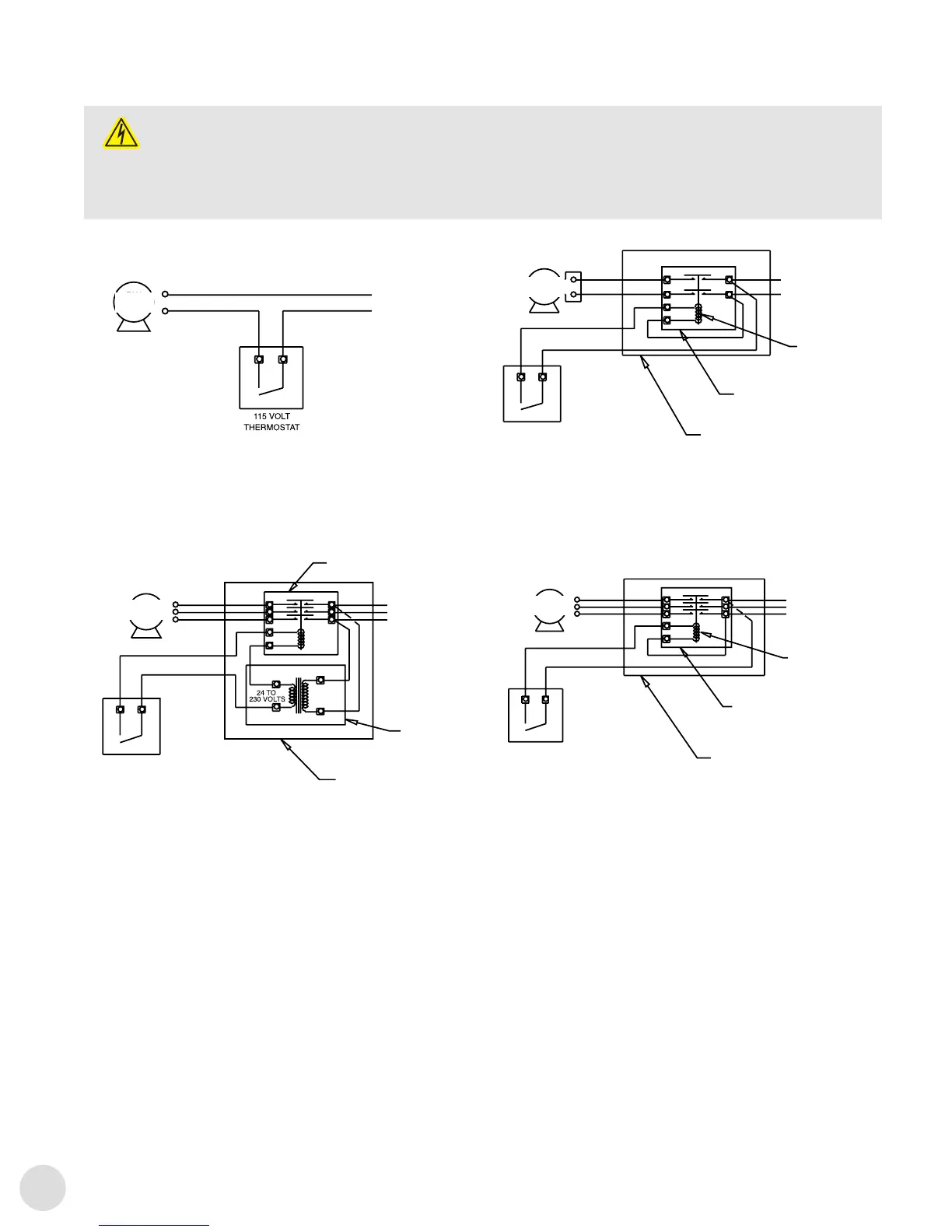
C.2 Schémas de câblage moteur
ATTENTION
ATTENTION. L'installation doit être effectuée par du
personnel qualié et conformément aux codes
électriques locaux.
Pour le câblage interne des appareils de commande
et des démarreurs, consultez le fabricant de l'appareil.
Le thermostat doit présenter une puissance électrique égale ou
supérieure à la puissance nominale de l'appareil de commande.
Pour le câblage du moteur du ventilateur, référez-vous au schéma
du moteur. Ces câbles doivent être connectés en série avec le
circuitdecommande du moteur.
THERMOSTAT
115VOLTS
MOTOR WIRING DIAGRAMS
CAUTION
Installation must be done by qualified personnel, and comply with local electrical codes.
For internal wiring of control devices and starters,
consult device manufacturer. The thermostat must have an electrical rating
equal to or exceeding the rating of the control device. For wiring of the fan motor, refer to diagram on
the motor. These wires must be connected in series with the motor control circuit.
FIGURE 7
- 6 -
MOTEUR DU
VENTILATEUR
MOTEUR DU
VENTILATEUR
MOTEUR DU
VENTILATEUR
MOTEUR DU
VENTILATEUR
THERMOSTAT24–230VOLTS
THERMOSTAT
230VOLTS
RELAIS CONTACTEUR 3PÔLES
(NON FOURNI)
THERMOSTAT
230VOLTS
COMMANDE THERMOSTATIQUE POUR MOTEURS
MONOPHASÉS208/230VOLTS
NEUTRE
COMMANDE THERMOSTATIQUE POUR
MOTEURS MONOPHASÉS 115VOLTS
COMMANDE THERMOSTATIQUE POUR
MOTEURS TRIPHASÉS 208/230VOLTS
TENSION
D'ALIMENTATION
115VOLTS
1PH
TENSION D'ALIMENTATION
208/230VOLTS
1PH
TENSION D'ALIMENTATION
460/600VOLTS
3PH
TENSION D'ALIMENTATION
208/230VOLTS
3PH
TRANSFORMATEUR
DE TENSION
(NON FOURNI)
BOBINE-CONTACTEUR
208/230VOLTS
RELAIS CONTACTEUR
3PÔLES (NON FOURNI)
PANNEAU DE CONTRÔLE
EXTERNE (NON FOURNI)
208/230VOLT
BOBINE-CONTACTEUR
RELAIS CONTACTEUR 2PÔLES
(NON FOURNI)
RELAIS DE CONTRÔLE EXTERNE
(NON FOURNI)
RELAIS DE CONTRÔLE EXTERNE
(NON FOURNI)
COMMANDE THERMOSTATIQUE POUR
MOTEURS TRIPHASÉS 460/600VOLTS