34
Réparation et remplacement
G. RÉPARATION ET REMPLACEMENT
ATTENTION
ATTENTION. Le système de chauffage ne doit être
entretenu que par du personnel qualié possédant
l'expérience nécessaire en matière d'équipement de
chauffage. Mettez le système de chauffage hors tension
avant toute réparation. Verrouillez l'interrupteur en
position «OFF» (ouverte) et/ou étiquetez l'interrupteur
pour éviter une mise sous tension inopinée. Les surfaces
du système de chauffage peuvent être chaudes.
Après la réparation d'un composant quelconque:
1. Vériez que les connexions électriques sont adéquates et
sécurisées.
2. Retirez tout corps étranger des boîtiers,
3. Installez et fermez tous les couvercles.
4. Assurez-vous que tous les dispositifs de xation sont bien
serrés.
5. Retirez tout corps étranger du système de chauffage.
6. Assurez-vous que l'air sort par les ventelles et que le
ventilateur tourne dans le sens inverse des aiguilles d'une
montre lorsqu'on le regarde depuis l'arrière du système de
chauffage (voir Figure8).
G.1 Moteur, ventilateur et grille du ventilateur
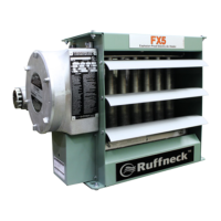
1. Retirez les boulons qui maintiennent le moteur sur son support.
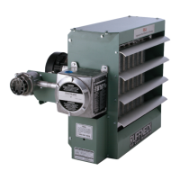
2. Retirez l'ensemble de protection du ventilateur en deux
pièces (voir Figure9).
3. Retirez le bloc moteur de son support.
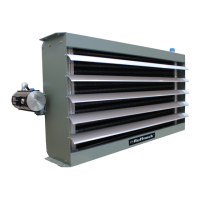
4. Avant de déposer le ventilateur, mesurez et notez
l'emplacement du moyeu du ventilateur comparativement
à l'arbre moteur (voir Figure10). Si le ventilateur est difcile
à démonter, utilisez un extracteur d'engrenage sur le
moyeu du ventilateur.
5. Pour remonter, positionnez le ventilateur sur l'arbre moteur
et serrez les vis de xation.
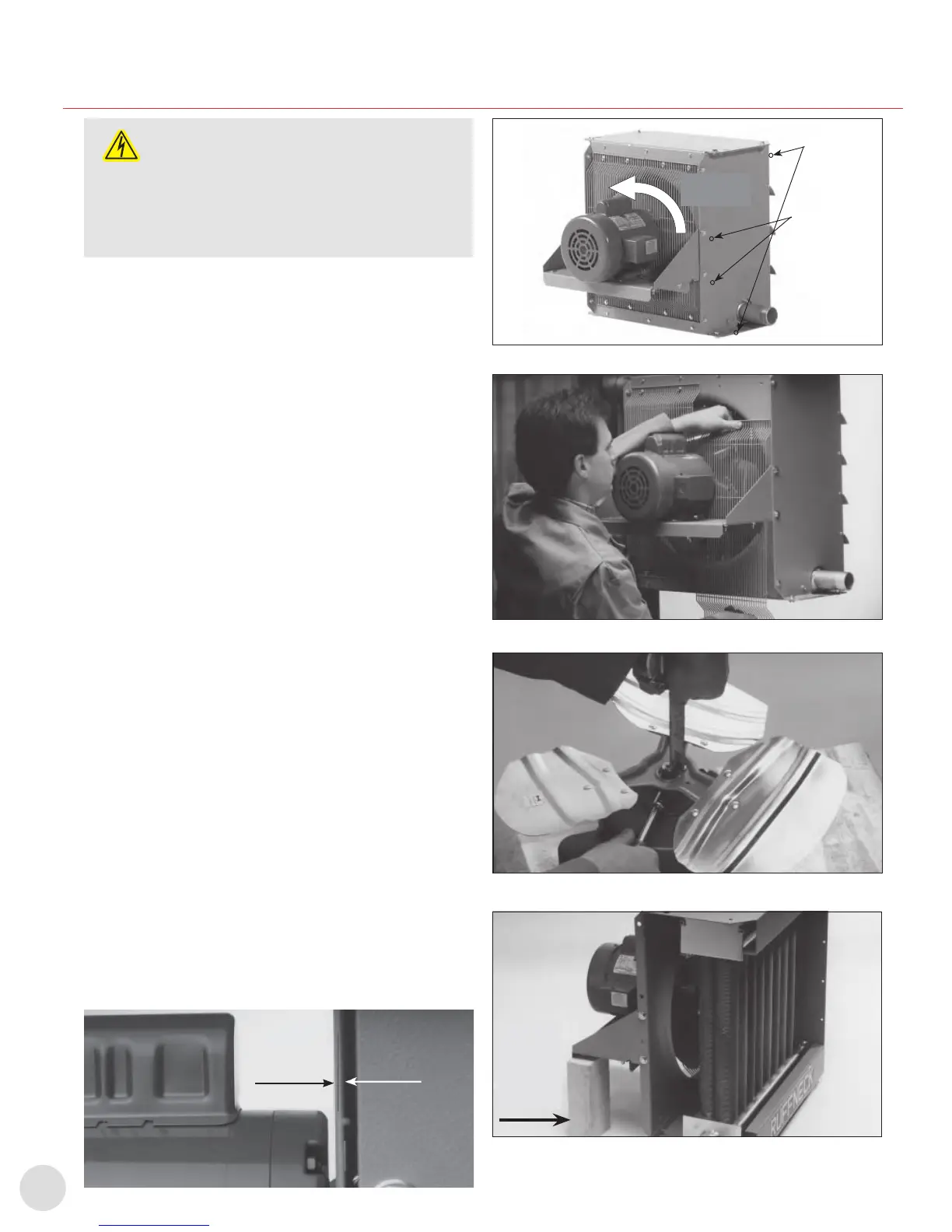
6. Placez le bloc moteur sur son support et xez la grille du
ventilateur sur l'armoire.
7. Centrez le ventilateur dans l'ouverture du capot. Laissez
un espace d'environ1/16" à3/16" (1,6à 4,8mm) entre le
moteur et la grille du ventilateur. (voir Figure9).
8. Boulonnez le moteur sur son support. Faites tourner
manuellement les pales du ventilateur pour vous assurer
qu'elles tournent librement avant la mise sous tension.
9. L'air doit sortir par les ventelles et le ventilateur doit tourner
dans le sens inverse des aiguilles d'une montre lorsqu'on
le regarde depuis l'arrière du système de chauffage (voir
Figure8).
1/16" à3/16"
(1,6à 4,8mm)
Figure7
REPAIR & REPLACEMENT
W A R NIN G
Heater should only be serviced by qualified
personnel with heating equipment experience.
Disconnect heater from power supply before
repairing heater. Lock the switch in the
off (open) position and/or tag the switch to
prevent unexpected power application.
Heater surfaces may be hot.
1. After repairing any component:
a. Check that electrical connections are correct and
secure.
b. Remove any foreign material from enclosures,
c. Install and secure all covers.
d. Ensure that all fasteners are tight.
e. Remove all foreign objects from heater.
f. Ensure air exits through louvers and fan rotates
counterclockwise when viewed from rear of heater
(see Figure 9).
MOTOR, FAN, AND
FAN GUARD
1. Remove bolts holding motor to the motor mount.
2. Remove the two piece fan guard assembly (see Figure 10).
3. Lift the motor assembly off the motor mount.
4. Before removing the fan, measure and record the location of
the fan hub on the motor shaft (see Figure 11). If fan is difficult
to remove, use a gear puller on the fan hub.
5. To reassemble, position fan on motor shaft and tighten set
screws.
6. Place motor assembly onto motor mount and fasten the fan
guard to cabinet.
7. Center fan in shroud opening. Leave approximately 1/16” to
3/16” (1.6 to 4.8 mm) gap between the motor and fan guard.
(see Figure 8).
8. Bolt motor to motor mount. Manually spin the fan blade to
ensure it rotates freely before applying power.
9. Air must exit through louvers and fan must rotate
counterclockwise when viewing from the rear of the heater
(see Figure 9).
- 8 -
FIGURE 9
FIGURE 10
FIGURE 11
FIGURE 8
FIGURE 12
1/16” to 3/16”
(1.6 to 4.8 mm)
Support
back of
heater
Fan
rotation
Air intake
Core
Bolts
Motor -
mount
Bolts
Boulons
centraux
Boulons
de xation
moteur
Rotation du
ventilateur
Entrée d'air
Figure8
REPAIR & REPLACEMENT
W A R NIN G
Heater should only be serviced by qualified
personnel with heating equipment experience.
Disconnect heater from power supply before
repairing heater. Lock the switch in the
off (open) position and/or tag the switch to
prevent unexpected power application.
Heater surfaces may be hot.
1. After repairing any component:
a. Check that electrical connections are correct and
secure.
b. Remove any foreign material from enclosures,
c. Install and secure all covers.
d. Ensure that all fasteners are tight.
e. Remove all foreign objects from heater.
f. Ensure air exits through louvers and fan rotates
counterclockwise when viewed from rear of heater
(see Figure 9).
MOTOR, FAN, AND
FAN GUARD
1. Remove bolts holding motor to the motor mount.
2. Remove the two piece fan guard assembly (see Figure 10).
3. Lift the motor assembly off the motor mount.
4. Before removing the fan, measure and record the location of
the fan hub on the motor shaft (see Figure 11). If fan is difficult
to remove, use a gear puller on the fan hub.
5. To reassemble, position fan on motor shaft and tighten set
screws.
6. Place motor assembly onto motor mount and fasten the fan
guard to cabinet.
7. Center fan in shroud opening. Leave approximately 1/16” to
3/16” (1.6 to 4.8 mm) gap between the motor and fan guard.
(see Figure 8).
8. Bolt motor to motor mount. Manually spin the fan blade to
ensure it rotates freely before applying power.
9. Air must exit through louvers and fan must rotate
counterclockwise when viewing from the rear of the heater
(see Figure 9).
- 8 -
FIGURE 9
FIGURE 10
FIGURE 11
FIGURE 8
FIGURE 12
1/16” to 3/16”
(1.6 to 4.8 mm)
Support
back of
heater
Fan
rotation
Air intake
Core
Bolts
Motor -
mount
Bolts
Figure9
REPAIR & REPLACEMENT
W A R NIN G
Heater should only be serviced by qualified
personnel with heating equipment experience.
Disconnect heater from power supply before
repairing heater. Lock the switch in the
off (open) position and/or tag the switch to
prevent unexpected power application.
Heater surfaces may be hot.
1. After repairing any component:
a. Check that electrical connections are correct and
secure.
b. Remove any foreign material from enclosures,
c. Install and secure all covers.
d. Ensure that all fasteners are tight.
e. Remove all foreign objects from heater.
f. Ensure air exits through louvers and fan rotates
counterclockwise when viewed from rear of heater
(see Figure 9).
MOTOR, FAN, AND
FAN GUARD
1. Remove bolts holding motor to the motor mount.
2. Remove the two piece fan guard assembly (see Figure 10).
3. Lift the motor assembly off the motor mount.
4. Before removing the fan, measure and record the location of
the fan hub on the motor shaft (see Figure 11). If fan is difficult
to remove, use a gear puller on the fan hub.
5. To reassemble, position fan on motor shaft and tighten set
screws.
6. Place motor assembly onto motor mount and fasten the fan
guard to cabinet.
7. Center fan in shroud opening. Leave approximately 1/16” to
3/16” (1.6 to 4.8 mm) gap between the motor and fan guard.
(see Figure 8).
8. Bolt motor to motor mount. Manually spin the fan blade to
ensure it rotates freely before applying power.
9. Air must exit through louvers and fan must rotate
counterclockwise when viewing from the rear of the heater
(see Figure 9).
- 8 -
FIGURE 9
FIGURE 10
FIGURE 11
FIGURE 8
FIGURE 12
1/16” to 3/16”
(1.6 to 4.8 mm)
Support
back of
heater
Fan
rotation
Air intake
Core
Bolts
Motor -
mount
Bolts
Figure10
REPAIR & REPLACEMENT
W A R NIN G
Heater should only be serviced by qualified
personnel with heating equipment experience.
Disconnect heater from power supply before
repairing heater. Lock the switch in the
off (open) position and/or tag the switch to
prevent unexpected power application.
Heater surfaces may be hot.
1. After repairing any component:
a. Check that electrical connections are correct and
secure.
b. Remove any foreign material from enclosures,
c. Install and secure all covers.
d. Ensure that all fasteners are tight.
e. Remove all foreign objects from heater.
f. Ensure air exits through louvers and fan rotates
counterclockwise when viewed from rear of heater
(see Figure 9).
MOTOR, FAN, AND
FAN GUARD
1. Remove bolts holding motor to the motor mount.
2. Remove the two piece fan guard assembly (see Figure 10).
3. Lift the motor assembly off the motor mount.
4. Before removing the fan, measure and record the location of
the fan hub on the motor shaft (see Figure 11). If fan is difficult
to remove, use a gear puller on the fan hub.
5. To reassemble, position fan on motor shaft and tighten set
screws.
6. Place motor assembly onto motor mount and fasten the fan
guard to cabinet.
7. Center fan in shroud opening. Leave approximately 1/16” to
3/16” (1.6 to 4.8 mm) gap between the motor and fan guard.
(see Figure 8).
8. Bolt motor to motor mount. Manually spin the fan blade to
ensure it rotates freely before applying power.
9. Air must exit through louvers and fan must rotate
counterclockwise when viewing from the rear of the heater
(see Figure 9).
- 8 -
FIGURE 9
FIGURE 10
FIGURE 11
FIGURE 8
FIGURE 12
1/16” to 3/16”
(1.6 to 4.8 mm)
Support
back of
heater
Fan
rotation
Air intake
Core
Bolts
Motor -
mount
Bolts
Support
arrière du
système de
chauffage
Figure11
 Loading...