Hardware Installation and Reference Guide Product Overview
33
2. Management Port LED
3. LED Mode Indicator
4. LED Mode Button
5. USB Port
6. Console Port
8. 10/100/1000Base-T Ethernet Port
9. 10GE SFP+ Port
10. Port LED
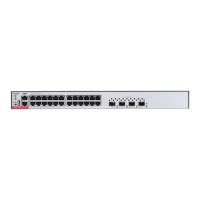
Back Panel
Figure 1-35 Back Panel of RG-S5300-24GT4XS-P-E
Power Supply
The RG-S5300-24GT4XS-P-E switch has a built-in power supply module. The back panel has an AC power plug.
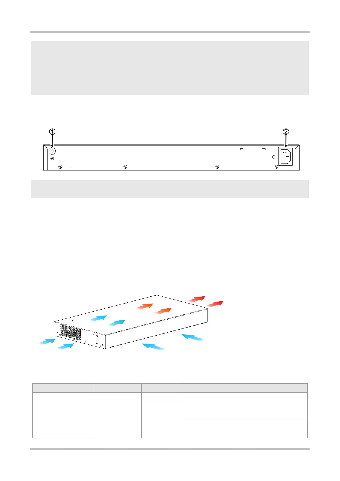
Cooling
The RG-S5300-24GT4XS-P-E switch adopts a left-to-right and front-to-right airflow to ensure normal operation. Maintain a minimum
clearance of 100 mm (3.94 in.) around the device for air circulation.
Figure 1-36 Airflow Direction
LED
System is not powered on.
System is being initialized. Continuous blinking indicates a
fault.
 Loading...