Hardware Installation and Reference Guide Product Overview
52
Moisture-proof, salt spray-proof, mold-proof, insulation-proof and leak-proof
Undervoltage protection, output overcurrent protection, output overvoltage protection and output
short circuit protection
The switch can communicate with the power supply module through I2C.
System supports 1+1 power redundancy when the PoE power consumption is less than 370 W. Dual
power supply modules are connected in parallel for current sharing.
In the power redundancy mode, the power supply module can be replaced when the system is
powered on.
When a power fault occurs, the output status LED turns off.
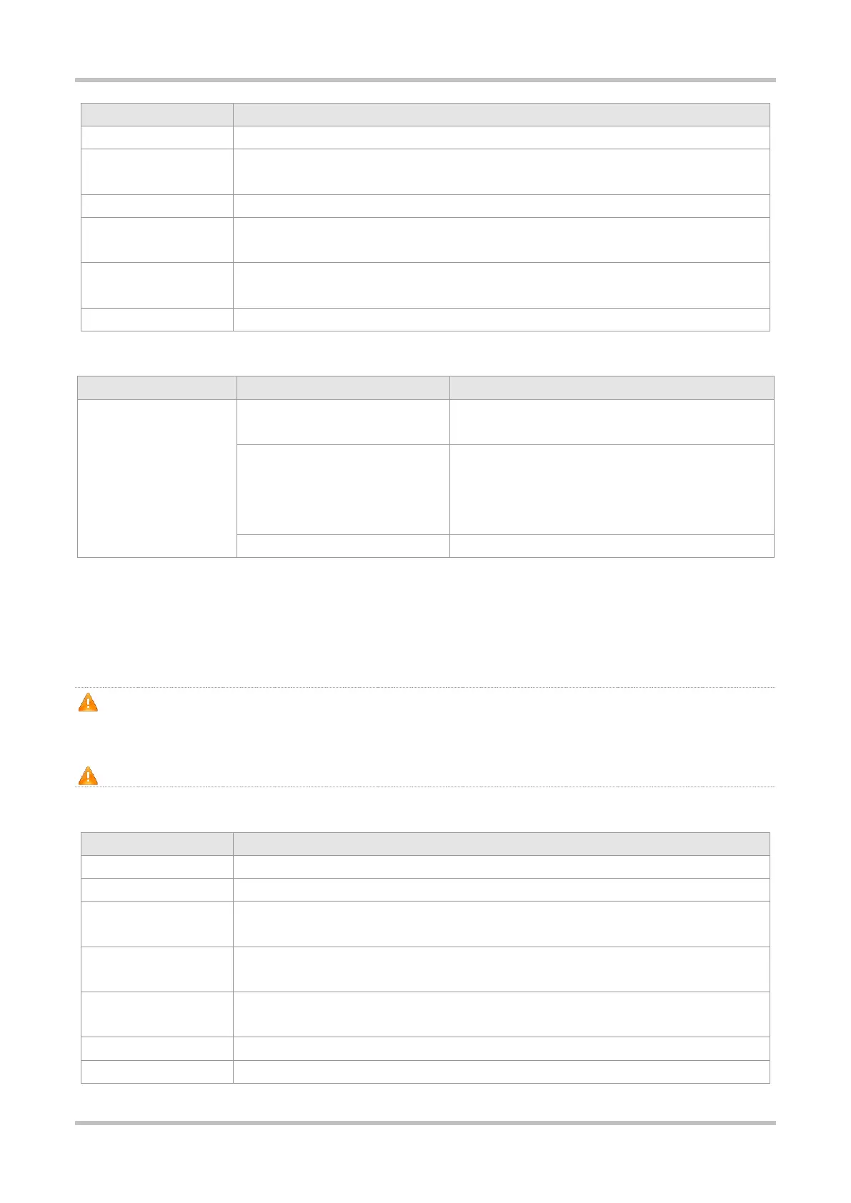
LED
The power supply module is not connected with a power
cord.
A power output error occurs, including fan fault, output
short-circuit, output overcurrent protection, output
overvoltage protection, power supply failure and overheat
protection.
The power supply module is outputing power normally.
1.13.6 RG-PA1000I-P-F Module
The RG-S5310-24GT4XS-P-E and RG-S5310-48GT4XS-P-E switches support the RG-PA1000I-P-F power module. The RG-PA1000I-P-F
module is an AC module (AC/HVDC input and DC output) providing an output voltage of 56 V and an output power of up to 1000 W
(PoE power: 740 W).
The switch can be powered on by either one power supply module or dual power supply modules. If both power supply modules
are used, the switch works in the power redundancy mode. The switch supports 1+1 power redundancy when the PoE power
consumption is less than 740 W.
At least one power supply module is required. If any slot is unoccupied, install a filler panel to enable proper airflow.
Specifications
RG-S5310-24GT4XS-P-E, RG-S5310-48GT4XS-P-E
Rated Input Voltage Range
AC Input: 100 V AC to 240 V AC, 50 Hz/60 Hz
HVDC Input: 240 V DC
Maximum Input Voltage
Range
AC Input: 90 V AC to 264 V AC, 47 Hz/63 Hz
HVDC Input: 192 VDC to 288 VDC
12 A (Input Voltage: 100 V AC)
8 A (Input Voltage: 200 V AC)
17.86 A (Input Voltage: 176 V AC to 290 V AC or 190 V DC to 290 V DC)
 Loading...