Hardware Installation and Reference Guide Installing the Switch
65
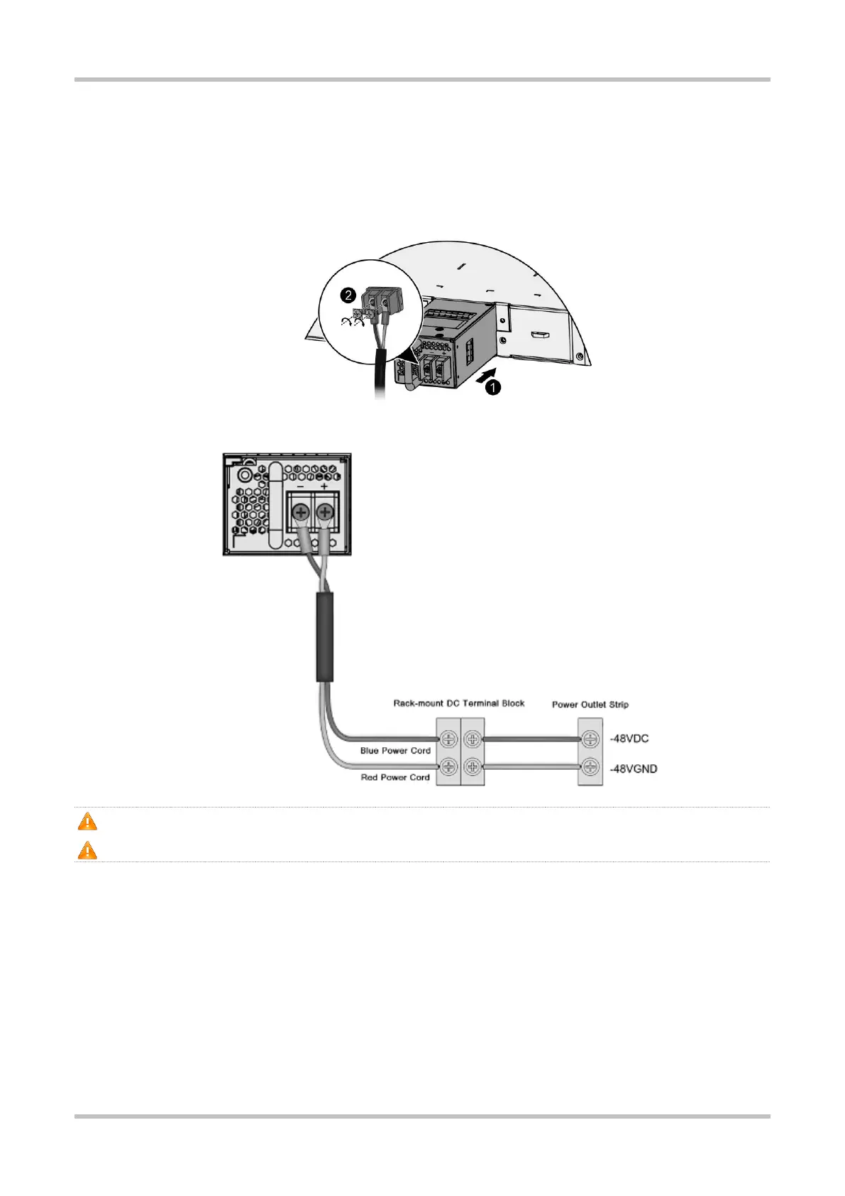
protective cover of the power input terminal, loosen the screw, and connect the terminals of the power cord. From left to right,
they are blue and red, and then cover the terminal protective cover.
3. Connect the other end of the power cord to the DC terminal block of the rack. Connect the blue power cord to -48 V DC, and the
red power cord to the -48 V GND.
Figure 3-9 Installing the Module
Figure 3-10 DC Terminal Block
Slide the module into the slot. Verify that the power supply module is in the correct orientation.
If you find it difficult to fully insert the module, pull the module out, align it to the guide rails and slide it into the slot again.
Removing the DC Power Supply Module
1. Press the latch on the module and grasp the handle with one hand. Place your other hand under the module to support its weight.
Pull the module fully out of the slot.
2. Install the filler panel in the empty slot. Put the removed module back into its packing materials.
Figure 3-11 Removing the Module
 Loading...