Hardware Installation and Reference Guide Product Overview
5
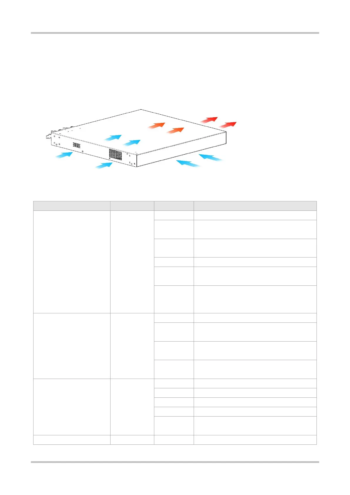
Cooling
The RG-S5310-24GT4XS-E switch adopts a left-to-right and front-to-right airflow to ensure normal operation. Maintain a minimum
clearance of 100 mm (3.94 in.) around the device for air circulation.
Figure 1-4 Airflow Direction
LED
System is not powered on.
System is being initialized. Continuous blinking
indicates a fault.
System is operating normally.
The temperature at the air intake and exhaust vents
exceeds the threshold.
1. The temperature at the air intake and exhaust vents
well exceeds the threshold.
2. The system is not functioning properly.
The power supply module is not seated.
The power supply module is seated and providing
power to the switch.
The model of the power supply module is not
supported or cannot be read.
The redundant power supply module is not functioning
properly or not connected with the AC power cord.
No link is detected for this port.
The port has made a successful 1000 Mbps link.
The port is sending and receiving traffic at 1000 Mbps.
The port has made a successful 10/100 Mbps link.
The port is sending and receiving traffic at 10/100
Mbps.
No link is detected for this port.
 Loading...