RG-ES206GS-P Series Switches Hardware Installation and Reference Guide Appendix C — Lightning Protection
- 28 -
grounded.
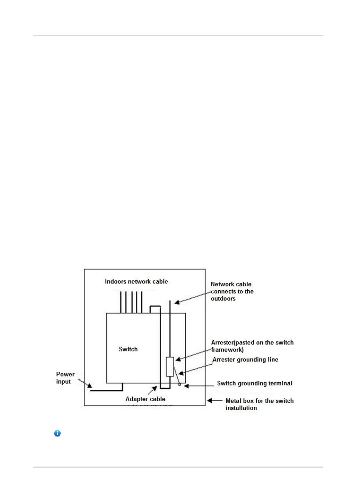
Installing the Ethernet Port Arrester
Connect an Ethernet port arrester to the switch to prevent the damage by lightning before connecting an
outdoor network cable to the switch.
Tools: Phillips screwdrivers or flat-head screwdriver, multimeter, and diagonal pliers
Installation Steps:
(1) Tear one side of the protective paper for the double-sided adhesive tape and paste the tape to the enclosure
of the Ethernet port arrester. Tear the other side of the protective paper for the double-sided adhesive tape
and paste the Ethernet port arrester to the switch enclosure. The paste position for the Ethernet port arrester
should be as close to the grounding terminal of the switch as possible. over any of its shares arising under
its Articles of Association;
(2) According to the distance between the switch grounding terminal and the Ethernet port arrester, cut the
grounding cable for the Ethernet port arrester and firmly crimp the grounding cable to the grounding terminal
of the switch.
(3) Use a multimeter to check whether the grounding cable for the arrester is in good contact with the grounding
terminal and the enclosure of the switch.
(4) Connect the arrester by using an adapter cable (note that the external network cable is connected to the IN
end, while the adapter cable connected to the switch is connected to the OUT end) and check whether the
service module LED is normal.
(5) Use a nylon cable tie to bind the power cords.
Figure C-2 Installation of the Ethernet Port Arrester
Note
● The Ethernet port arrester is only for the 10/100 Mbps copper ports with an RJ-45 connector.
 Loading...