RG-ES206GS-P Series Switches Hardware Installation and Reference Guide Appendix C — Lightning Protection
- 27 -
Appendix C — Lightning Protection
Installing an AC Power Arrester (Lightning Resistance Socket)
When an AC power cord is introduced from outdoors and directly connected to the power port of the switch, the
AC power port must be connected to an external lightning protection power strip to protect the switch against
lightning strokes. The lightning resistance socket can be fixed on the rack, workbench, or wall in the machine
room by using cable ties and screws. AC power enters the lightning protection power strip and then enters the
switch.
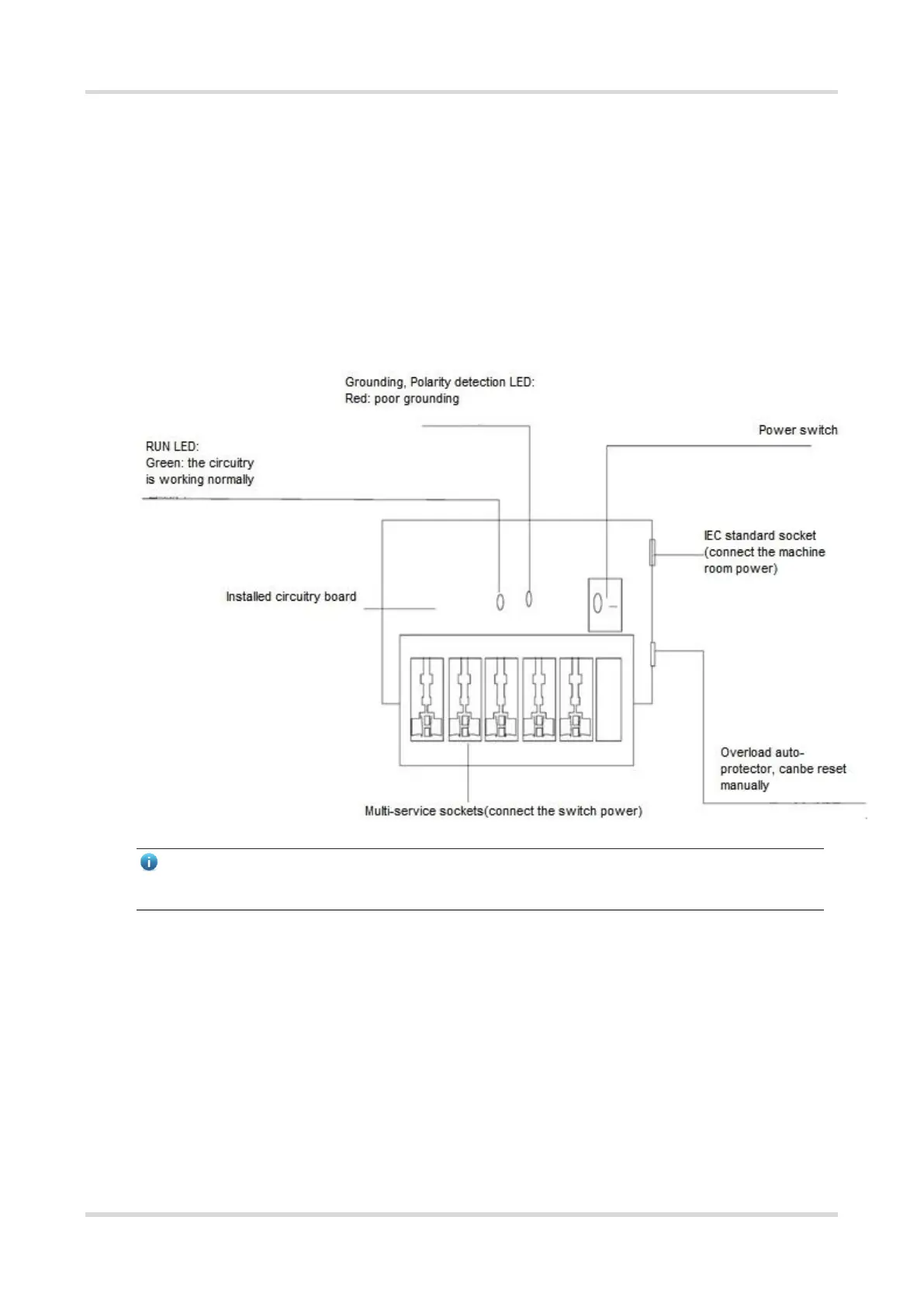
Figure C-1 Power Arrester
Note
The power arrester is not delivered with the switch. Please purchase it based on actual requirements.
Important points:
Make sure that the PE terminal of the power arrester is well grounded.
After the AC power plug of the switch is connected to the socket of the power arrester (lightning resistance
socket), the lightning protection function is implemented only if the RUN indicator is green and the ALARM
indicator is OFF.
If the ALARM indicator on the power arrester is red, check whether it is caused by poor grounding
connection or by the reversed connection of the Null and Live lines. The detection method is as follows: Use
a multimeter to measure the polarity of the power socket for the arrester when the indicator is red. If the N
line is on the left and the L line is on the right (facing the socket), the arrester's PE terminal is not grounded.
If not, the polarity of the arrester power cord should be reversed. In this case, you should open the power
arrester and rectify the polarity of the connection. If the indicator is still red, the arrester's PE terminal is not
 Loading...