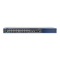
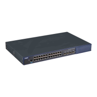
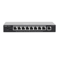
Hardware Installation and Reference Guide Product Overview
11
Figure 1-16 Airflow Direction of RG-S5000-10GT2MS-E Switch
The switch should be installed at least 1 U (44.45 mm/1.75 in.) away from the neighbor device for normal heat
dissipation.
LED
The system is being initialized.
The system is operating normally.
A system over-temperature alarm is
generated.
1. The temperature severely exceeds the
threshold, and the system restarts.
2. A system failure occurs.
10/100/1000 Mbps
copper port status
LED
No link is detected for this port.
The port has a 10/100/1000 Mbps link up.
The port is receiving or transmitting data.
No link is detected for this port.
The port is receiving or transmitting data.
The optical attenuation value exceeds the
value specified in the communication
quality requirements.
The optical module is in position, but the
optical module fails or an optical link failure
occurs.
 Loading...
