TECHNICAL MANUAL FOR THE RDR BL3 - V1.1 DRIVE ROLLER Rev. 21/09/2018 page 28
9.3 Adjusting Drive Roller speed
Drive Roller (optional) speed is adjusted as follows:
- 0 - 2.5 VDC : the Drive Roller remains stationary, but in braking status (speed = 0 m/s).
The braking torque depends on the reduction ratio used.
- 2.5 - 10 VDC : the Drive Roller adopts the speed comprised between min and max,
proportionally to the applied voltage
- 10 - 24 VDC : the Drive Roller always adopts its maximum speed (declared on the catalog).
To set an intermediate speed comprised between minimum and maximum, send a signal between 2.5 and 10
VDC to the yellow wire (START).
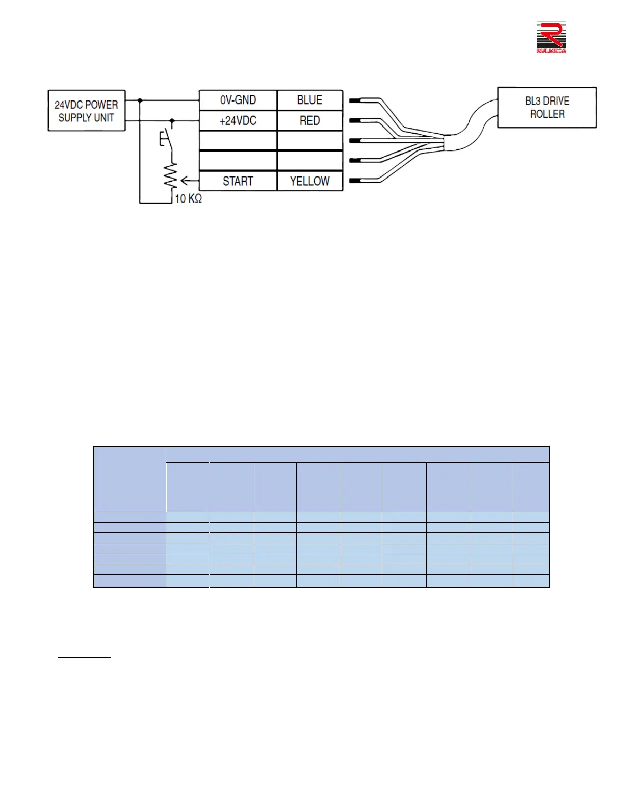
For this purpose, a 10 KΩ potentiometer (or a fixed resistance of suitable value) can be connected between the
RED wire and the YELLOW wire as shown in the wiring diagram.
The switch serially placed to the resistance can be used to drive or stop the Drive Roller.
Specifically, the speed values of the voltage applied to the YELLOW wire are shown in the following table:
By adjusting speed, acceleration and/or deceleration ramps can also be created by setting the variation in the
reference voltage/speed in the desired time, making use of a PLC with an analogue voltage output that can be
varied by the program.
WARNING:
- If you wish to use the +24VDC (red wire) and only one potentiometer to regulate the speed of several
Drive Rollers, there is no limit to the number of Drive Rollers that can be connected.
- NEVER use the Drive Roller's master switch to stop it. Emergency stops must be handled by
disconnecting the VAC supply of the of the power supply unit.