TECHNICAL MANUAL FOR THE RDR BL3 - V1.1 DRIVE ROLLER Rev. 21/09/2018 page 32
11 DRIVE ROLLER CURRENT ABSORPTION TABLES
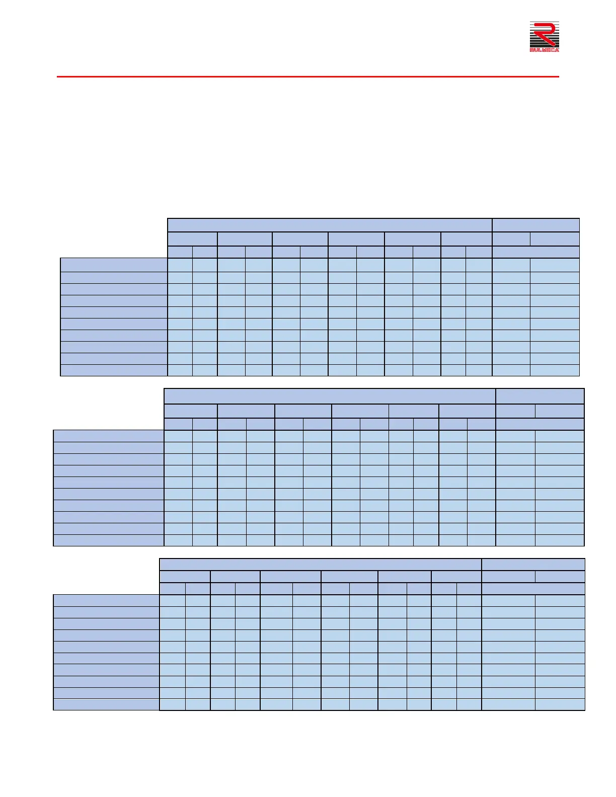
The following tables have been obtained from empirical tests. The information given may help the customer choose the correct
power supply unit on the basis of the current absorbed by the single RDR BL-3 Drive Roller.
The currents were defined by the variation of the load on the rollers and the variation in the number of driven rollers. The tests
were run using Poly-V belts as the transmission system.
The data given (inrush currents [Sp] and speed currents [Nom]) then have to be adapted to the single situation, taking account
of the other variables that may affect the results.
The tests were run using series 135 V1 driven rollers in the Poly-V version having C=600 mm values using 2-rib Poly-V belts
(not recommended if weights above 50 Kg have to be handled).
As the currents increase, the start/stop cycles have to decrease in order to prevent the motor overheating. The definition of
maximum acceptable current varies with the change in environmental data (ambient temperature). High ambient temperatures
reduce the possibility of dispersing the temperature, as does covering the tube with PVC or other materials.
11.1 Reduction ratio 12:1
Current only Drive Roller
Drive Roller + 10 Rollers
Drive Roller + 12 Rollers
Drive Roller + 14 Rollers
Drive Roller + 16 Rollers
Drive Roller + 18 Rollers
11.2 Reduction ratio 16:1
Current only Drive Roller
Drive Roller + 10 Rollers
Drive Roller + 12 Rollers
Drive Roller + 14 Rollers
Drive Roller + 16 Rollers
Drive Roller + 18 Rollers
11.3 Reduction ratio 24:1
Current only Drive Roller
Drive Roller + 10 Rollers
Drive Roller + 12 Rollers
Drive Roller + 14 Rollers
Drive Roller + 16 Rollers
Drive Roller + 18 Rollers
 Loading...