BA.GB.12-27409-05-07-FTA-jr
2.1.2 Details about the Steiger-superstructure ..................................2-3
2.1.2.1 Main data .................................................................................2-3
2.1.2.2 Stabilizing jacks .......................................................................2-4
2.1.2.3 Boom .......................................................................................2-4
2.1.2.4 Working cage ...........................................................................2-5
2.1.2.5 Control / Drive ..........................................................................2-6
2.1.2.6 Noise level ...............................................................................2-6
2.1.3 Details about chassis ...............................................................2-6
2.1.4 Static and dynamic controls by the manufacturer .....................2-7
2.2 Type plate, CE-mark and inspection plate 2-8
2.3 Working ranges 2-9
2.3.1 Working range with fully extended jacks ................................ 2-10
2.4 Beaufort-Scale 2-11
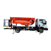
3 Description of the Ruthmann-Steiger 3-1
3.1 Construction of the Steiger 3-1
3.1.1 Description of individual constructional components ................3-2
3.1.1.1 Steiger-substructure .................................................................3-2
3.1.1.2 Stabilizing jacks .......................................................................3-2
3.1.1.3 Boom .......................................................................................3-2
3.1.1.4 Working cage ...........................................................................3-3
3.1.1.4.1 Socket 230 Volts ......................................................................3-3
3.1.1.4.2 Line to working cage for air or water resp. (Optional extra) ......3-4
3.2 Hydraulic System 3-5
3.3 Description of the control system 3-6
3.3.1 Battery voltage control .............................................................3-6
3.3.2 Stabilizing jack base .................................................................3-7
3.3.3 The Steiger's movements .........................................................3-8
3.3.4 Switch boxes ............................................................................3-9
3.3.5 Control stand „Cage control“ .................................................. 3-10
3.3.6 Control stand „Emergency control“ ......................................... 3-11
3.3.7 Electrical locking devices ....................................................... 3-11
3.3.8 Limitation of outreach depending on the angle of rotation ...... 3-12
3.3.9 Automatic levelling device ...................................................... 3-13
3.3.10 Automatic adjustment of the working cage and of the
telescope................................................................................ 3-13
3.3.11 Soft starting and soft stopping of Steiger movements ............ 3-13
3.3.12 Cushioning of final positions ................................................... 3-14
3.3.13 Securing of the driver’s cab and of the rear stabilising jacks
when rotating or lowering the boom ....................................... 3-14
3.3.14 Memory .................................................................................. 3-15
3.3.15 Automated positioning aid for centre position of boom ........... 3-15
3.3.16 Moving the Steiger into the basic position automatically ......... 3-15
 Loading...